
“A rare characteristic of the SMAP Project is its emphasis on serving both basic Earth System science as well as applications in operational and practice-oriented communities.”
Contents of Full Handbook
1. Introduction and Background
2. Mission Overview
3. Instrument Design and L1 Data Products
4. Soil Moisture Data Products
5. Value-Added L4_SM Soil Moisture Product
6. Carbon Cycle Data Products
7. Science Data Calibration and Validation
8. NASA SMAP Applications Program
9. SMAP Project Bibliography
SMAP Handbook Excerpts on ASF’s Roles
The Alaska Satellite Facility (ASF) is one of four ground stations that support the SMAP mission and one of two NASA DAACs that distribute SMAP data. The SMAP baseline science data products will be generated within the project’s Science Data System and made available publicly through the two NASA-designated Earth-science data centers. The ASF Synthetic Aperture Radar (SAR) Distributed Active Archive Center (DAAC) will provide Level 1 radar products, and the National Snow and Ice Data Center (NSIDC) DAAC will provide all other products. The excerpts below from the SMAP Handbook focus on ASF’s roles. Read more about ASF
Ground Data System (GDS)
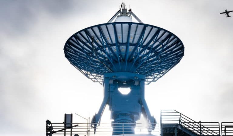
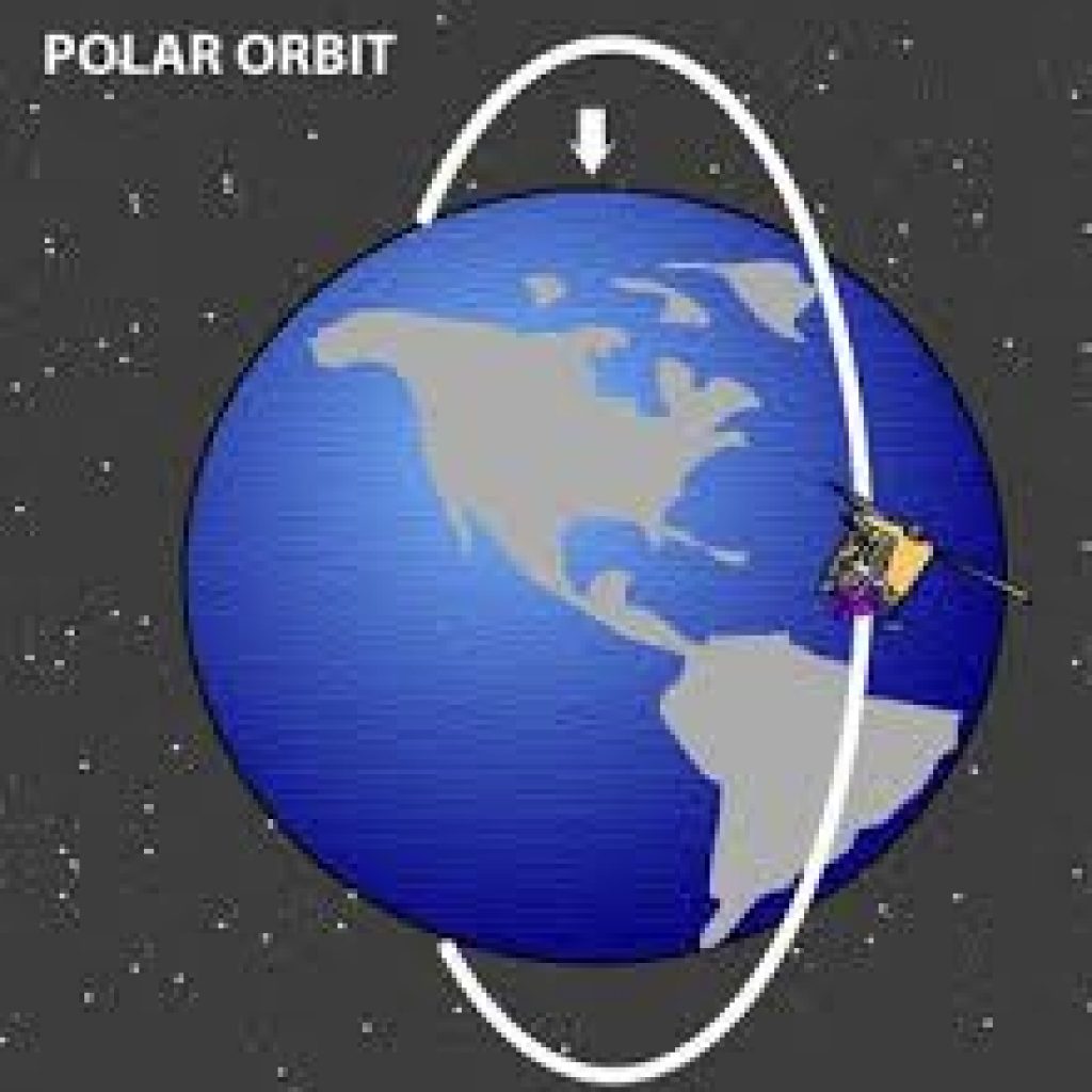
The primary path for commanding the SMAP observatory and returning science and engineering data is through three northern-hemisphere tracking stations and one southern-hemisphere station in Antarctica. Data return at the northern-hemisphere stations is via 11.3-m antennas located at Wallops, Virginia (WGS), Fairbanks, Alaska (ASF), and Svalbard Island, Norway (SGS). Data return at the southern-hemisphere station is via the 10-m antenna at McMurdo Station, Antarctica (MGS). The table below gives characteristics of the four stations and average contact statistics from the science orbit. Because SMAP is in a near-polar orbit, the higher latitude stations have more frequent contact opportunities.
| Ground Station | Antenna | Latitude | Average # of Contacts per day* | Average Coverage Minutes/day* |
|---|---|---|---|---|
| Svalbard (SGS) Norway | 11.3 m | 78.2ºN | 10.3 | 88.3 |
| Fairbanks (ASF) Alaska | 11.3 m | 64.9ºN | 6.8 | 53.7 |
| Wallops (WGS) Virginia | 11.3 m | 37.9ºN | 3.3 | 25.8 |
| McMurdo (MGS) Antarctica | 10.0 m | 77.8ºS | 10.4 | 90.7 |
ASF DAAC Support of NASA Missions
The ASF DAAC provides support for NASA and NASA-partner missions assigned to it by the Earth Science Data and Information System (ESDIS) Project. The ASF DAAC has extensive experience managing diverse airborne and spaceborne mission data, working with various file formats, and assisting user communities to further the use of SAR data.
These efforts are facilitated, in part, by ASF Scientists and Data Managers, who interact with mission teams, provide subject matter expertise, inform data and metadata formats, evaluate data structure and quality, and address data support needs. A key project component at ASF is the core product team, which provides integration of new datasets into the ASF data system and ensures efficient coordination and support of each mission. The team members have mission-specific expertise and consist of the following personnel:
- The Project Manager is the team leader who oversees mission activities at ASF and coordinates with external groups.
- The Product Owner is a primary product stakeholder and oversees ingest, archive, documentation, and distribution of data products as well as managing interactions with mission and ASF scientists and other stakeholders.
- The User Services Representative ([email protected]) supports data users with products and software tools and communicates user feedback or suggestions for improvement to the Project Manager and Product Owner.
- Software Engineers design, develop, and maintain software for the acquisition, processing, archiving, and distribution of satellite and aerial remote sensing data.
- Software Quality Assurance Technicians provide software and web-based-application testing prior to delivery to the production data system to ensure integrity, quality, and overall proper functionality through testing methods to uncover program defects, which in turn are reported to software engineers.
- The Technical Science Writer composes and edits a variety of ASF materials, from newsletter articles to technical documentation.
The core product team’s responsibilities for data management include:
- Ingesting, cataloging, archiving, and distributing data
- Providing guidance on file formats and integration of new file formats into the ASF data system
- Describing data products and producing user manuals and guide documents
- Creating metadata and exporting it to CMR and GCMD (Global Change Master Directory)
- Ensuring accurate metrics are reported to EMS (ESDIS Metrics System)
- Designing, developing, and deploying specialized data portals that allow online access to data products and information
- Creating software tools for data interpretation and analysis
- Assisting users with the selection and usage of data
ASF also supports NASA and partner missions through the operation of a ground station with two 11-m antennas, providing complete services, including data downlinking, commanding, and range/Doppler tracking. ASF is part of the NASA Near Earth Network (NEN) supporting a variety of low-Earth-orbit spacecraft.
ASF DAAC Data Systems
The ASF DAAC operates a custom data system designed, implemented, and supported by DAAC personnel. During its evolution, the ASF data system has moved from using primarily custom software on capital equipment to commodity hardware and commercial off-the-shelf (COTS) software and hardware solutions. This has greatly lowered development and maintenance costs for the data system, while simultaneously providing a higher level of performance. The ASF DAAC data system provides the following capabilities:
Data Ingest
- Automated data ingest occurs from the ASF ground station as well as external data providers in a variety of media and formats.
- Ingested data are pre-processed when necessary, providing browse or derivative products.
Data Archive
- The central ASF data system archive is provided by a Data Direct Networks gridscaler storage system.
- This system provides direct access to over 1 PB of processed data as well as the capability for automated backups to an offsite location.
- Raw data are held in a robotic silo for access by the processing system. ASF maintains a backup in an external location in case of silo failure.
Data Distribution
- ASF provides direct http access to DAAC data products and utilizes NASA’s User Registration System (URS) for user authentication.
- NASA data are provided to public users with no restrictions. Partner data are provided to NASA-approved users through URS for authentication and ASF’s internal database for access control.
- The data system provides web-based access to the archive through Vertex. Vertex supports the data pool with direct download of processed data.
- Through custom portals and applications, the DAAC provides additional services such as mosaic subsetting, mosaicking, and time-series analysis.
Data Support
- ASF DAAC exports relevant metadata to NASA’s ECHO system.
- ASF DAAC exports ingest, archive, and download metrics to NASA’s EMS system.
- ASF DAAC assists users with data discovery and usage, maintains product documentation and use guides, and supports feedback between the ASF user community and the core product teams.
SMAP at ASF DAAC
ASF provides a variety of services, software tools, and user support to address the needs of the SMAP user community. The ASF core project team will leverage on-going collaborations with the SMAP Project to identify and prioritize SMAP user community needs, which in turn will inform development and implementation of data support and value-adding services for the mission. The SMAP website at ASF will serve as an interactive data portal, providing users with relevant documentation, custom tools and services, and ancillary data and resources.
Post-Launch SMAP Data
ASF will ingest, distribute, archive, and support postlaunch Level 1 radar products for the SMAP mission. ASF will receive the Level 1 radar products from the SMAP Science Data System at the Jet Propulsion Laboratory (JPL) in Pasadena, California.
Non-SMAP Data of Interest to SMAP
ASF will cross-link from the SMAP website to data collections that complement SMAP data and are of interest to the user community. Some of these collections are distributed by ASF, including the following:
- Airborne Microwave Observatory of Subcanopy and Subsurface (AirMOSS) data products
- Jet Propulsion Laboratory Uninhabited Aerial Vehicle SAR (UAVSAR) data products
- Making Earth System Data Records for Use in Research Environments Inundated Wetlands (MEaSUREs) data products
- Advanced Land Observing Satellite-Phased Array L-band SAR (ALOS PALSAR)
- Japanese Earth Resources Satellite-1 (JERS-1) image data and mosaics
Acronyms
| Acronym | Definition |
|---|---|
| ASF | Alaska Satellite Facility |
| ATBDs | Algorithm Theoretical Basis Documents |
| Cal/Val | Calibration and Validation |
| DAAC | Distributed Active Archive Center |
| HDF5 | Hierarchical Data Format |
| JPL | Jet Propulsion Laboratory |
| NASA | National Aeronautics and Space Administration |
| NSIDC | National Snow and Ice Data Center |
| ROP | Routine Observations Phase |
| SMAP | Soil Moisture Active Passive |
| SAR | Synthetic Aperture Radar |
| SDS | Science Data System |
| SOP | Science Operations Phase |
| UTC | Coordinated Universal Time |
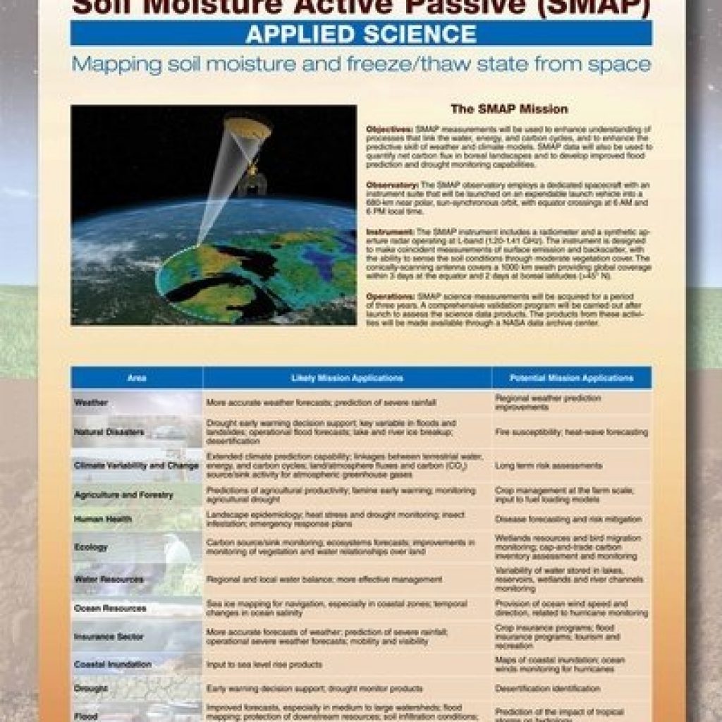
SMAP’s spaceborne Earth-observation mission will enable global mapping of soil-moisture and freeze-thaw state with unprecedented accuracy, resolution, and coverage. SMAP science objectives are to acquire space-based, hydrosphere-state measurements over a three-year period to:
- Understand processes that link the terrestrial water, energy, and carbon cycles
- Estimate global water and energy fluxes at the land surface
- Quantify net carbon flux in boreal landscapes
- Enhance weather-forecast and climate-forecast skills
- Develop improved flood-prediction and drought-monitoring capabilities
Water and Energy Cycles, Weather, and Climate
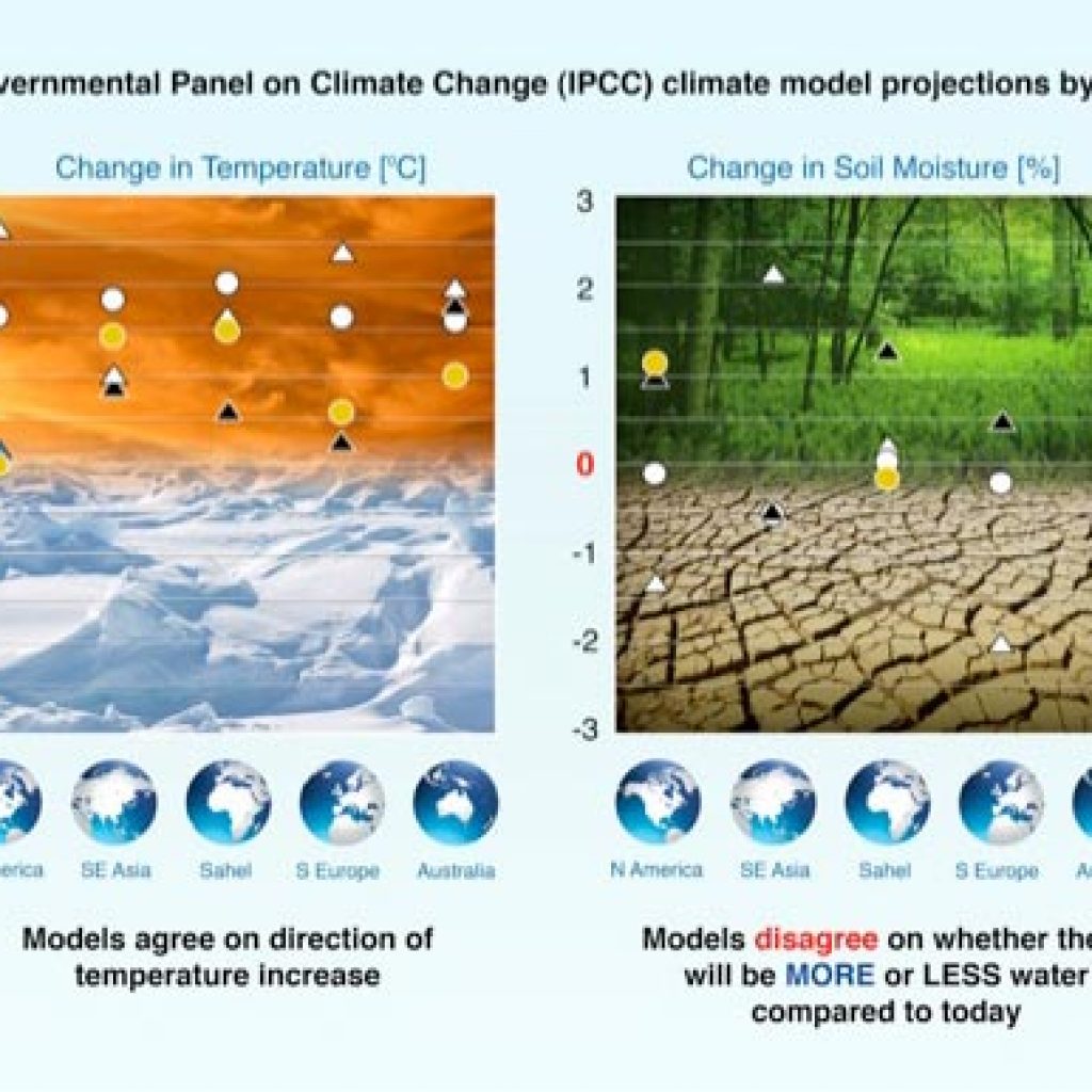
Recent model simulations of the effects of greenhouse gases on climate show that current models agree quite well in predicting temperature change but disagree significantly in predicting surface-moisture change and water-resource availability. Accurate soil-moisture information, such as data from SMAP, will improve the performance and enhance the predictive ability of numerical weather-prediction models and seasonal climate models. Soil moisture is a key control on evaporation and transpiration at the land-atmosphere boundary. Because vaporizing water requires large amounts of energy, soil-moisture control also has a significant impact on the surface energy flux. Soil-moisture variations affect the evolution of weather and climate, particularly over continental regions.
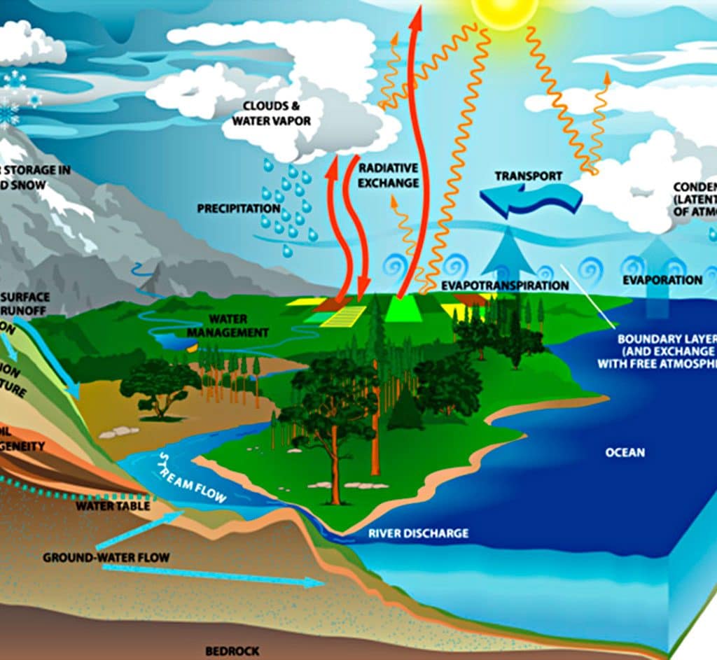
Earth’s water cycle involves the transfer and storage of water in the atmosphere, on the planet’s surface, underground, and by life in its many forms.
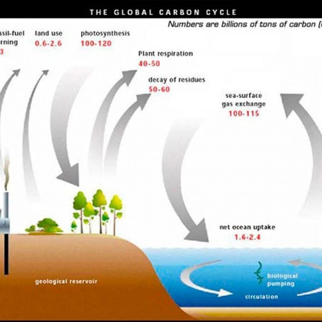
Carbon Cycle and Ecosystems
Soil moisture and its freeze-thaw state are also key determinants of the global carbon cycle. Carbon uptake and release in boreal landscapes is one of the major sources of uncertainty in assessing the carbon budget of the Earth system (the so-called missing carbon sink). The SMAP mission will quantify the nature, extent, timing, and duration of landscape seasonal freeze-thaw state transitions that are key to the estimation of terrestrial carbon sources and sinks. SMAP freeze-thaw state measurements will also contribute to understanding how ecosystems respond to and affect global environmental change, improving regional mapping and prediction of boreal-Arctic ecosystem processes.
SMAP Goals
The SMAP Project is designed to collect measurements of surface soil moisture and freeze-thaw state, together termed the hydrosphere state. Soil moisture is defined in terms of volume of water per unit volume of soil. Freeze-thaw state is defined as the phase of the water contained within the landscape including soil and vegetation. To meet the goals of science and applications users, SMAP must:
- Resolve hydrometeorological water and energy flux processes and extend weather and flood forecast skill, spatial resolution of 10 km and temporal resolution of 3 days are required.
- Resolve hydroclimatological water and energy flux processes and extend climate and drought forecast capability, spatial resolution of 40 km and temporal resolution of 3 days are required.
- Quantify net carbon flux in boreal landscapes, spatial resolution of 3 km and temporal resolution of 2 days are required. In addition, the SMAP mission will validate a space-based measurement approach that could be used for future systematic hydrosphere state monitoring missions.
SMAP News
NASA Soil Moisture Radar Ends Operations; Mission Science Continues
NASA Focused on Sentinel as Replacement for SMAP Radar
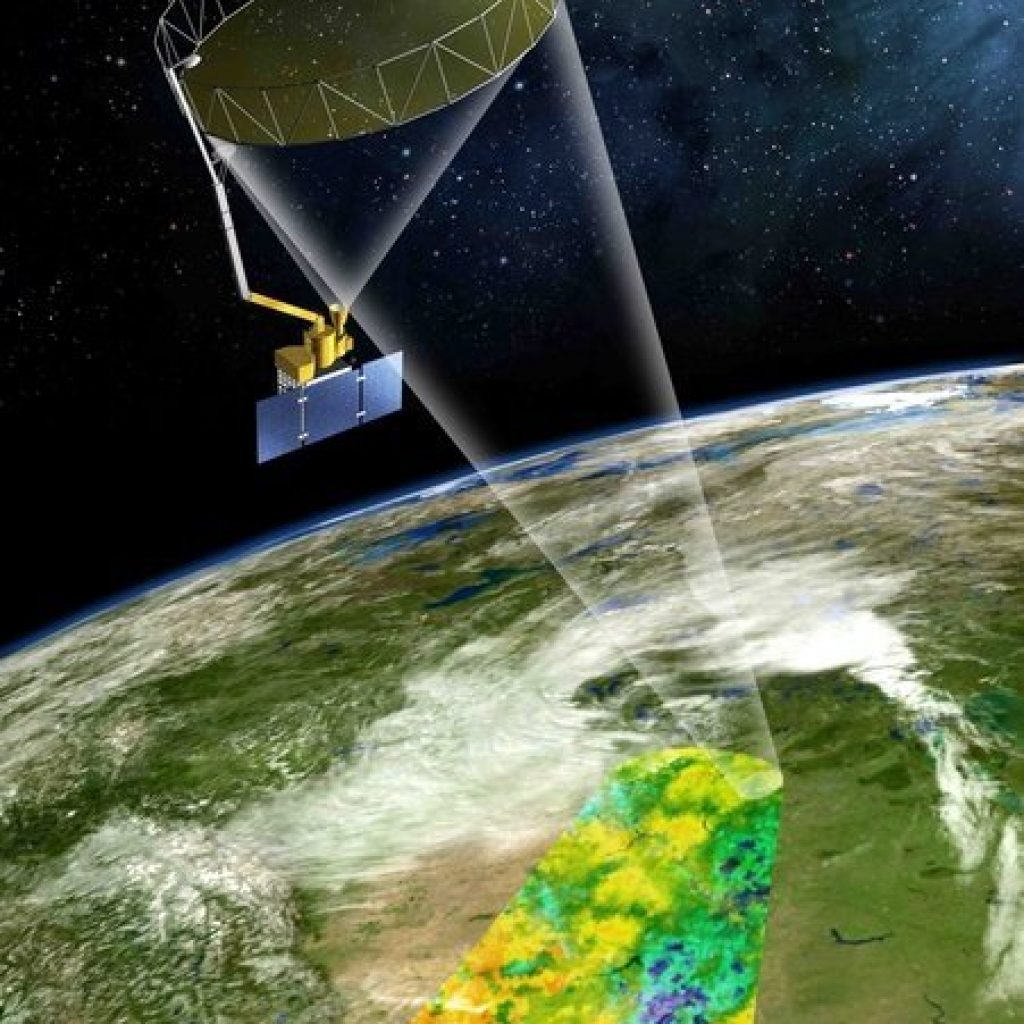
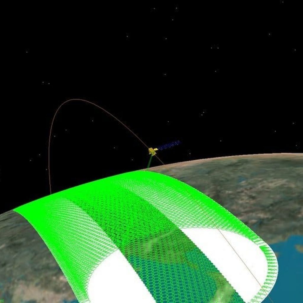
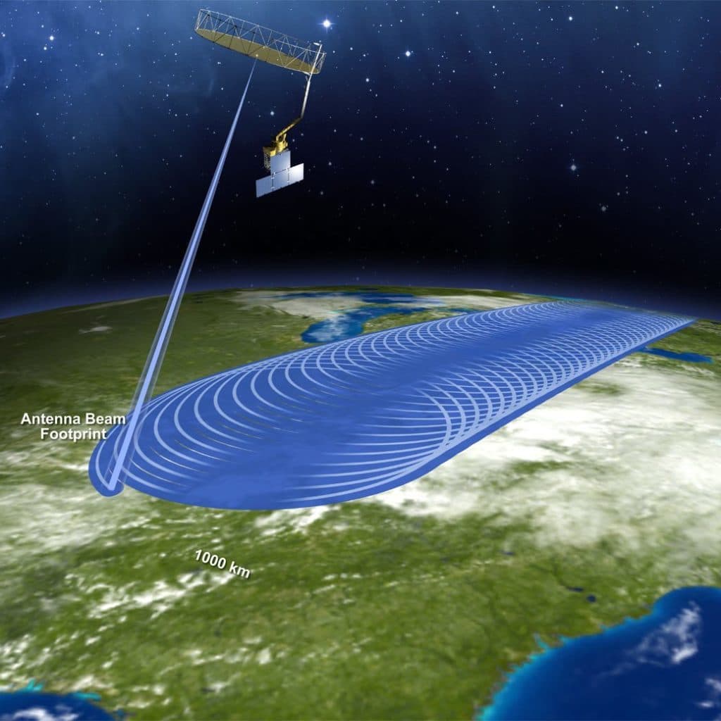
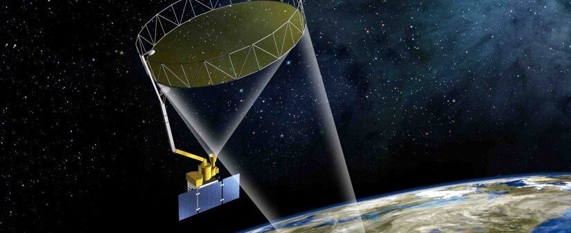
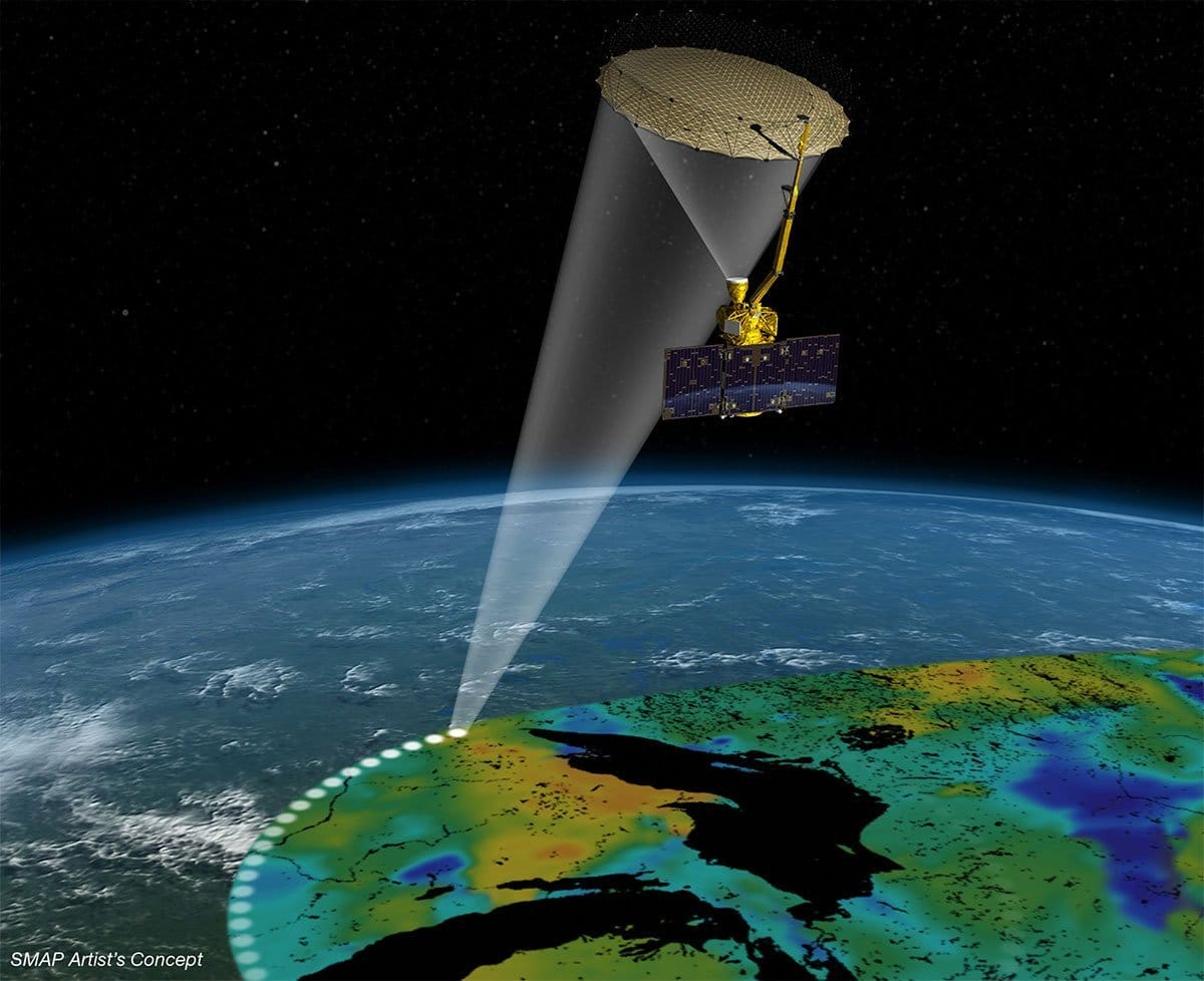
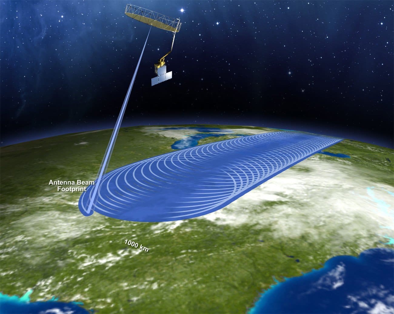
Soil Moisture Passive Active (SMAP) is a remote-sensing observatory with two instruments — a synthetic aperture radar (SAR) and a radiometer — that map soil moisture and determine the freeze or thaw state of the area being mapped. Both instruments help map soil-moisture content, and unique properties of SAR enable the freeze-thaw mapping. Externally, the instruments share a common, 20-foot mesh antenna and a feed assembly. Inside the spacecraft, their electronics differ. When combined, the SMAP radar and radiometer deliver high-accuracy, high-resolution global maps of the Earth’s soil moisture and freeze-thaw state.
The radar actively sends pulses of radio waves down to a spot on Earth and measures the echo that returns microseconds later. The strength and “shape” of the echoes can be interpreted to indicate the moisture level of the soil, even through moderate levels of vegetation. The radiometer passively detects radio waves emitted by the ground from the same small area. The strength of the emission indicates temperatures.
News: NASA Soil Moisture Radar Ends Operations; Mission Science Continues
News: NASA Focused on Sentinel as Replacement for SMAP Radar
 |  |  |
|---|---|---|
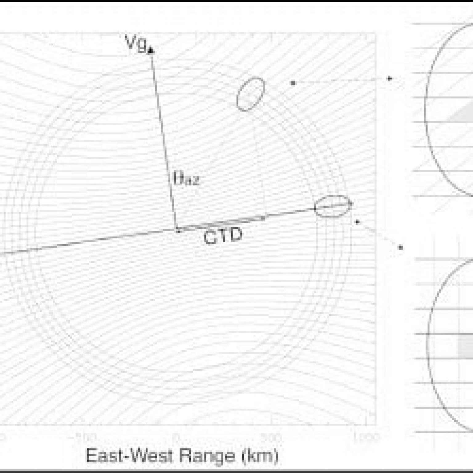
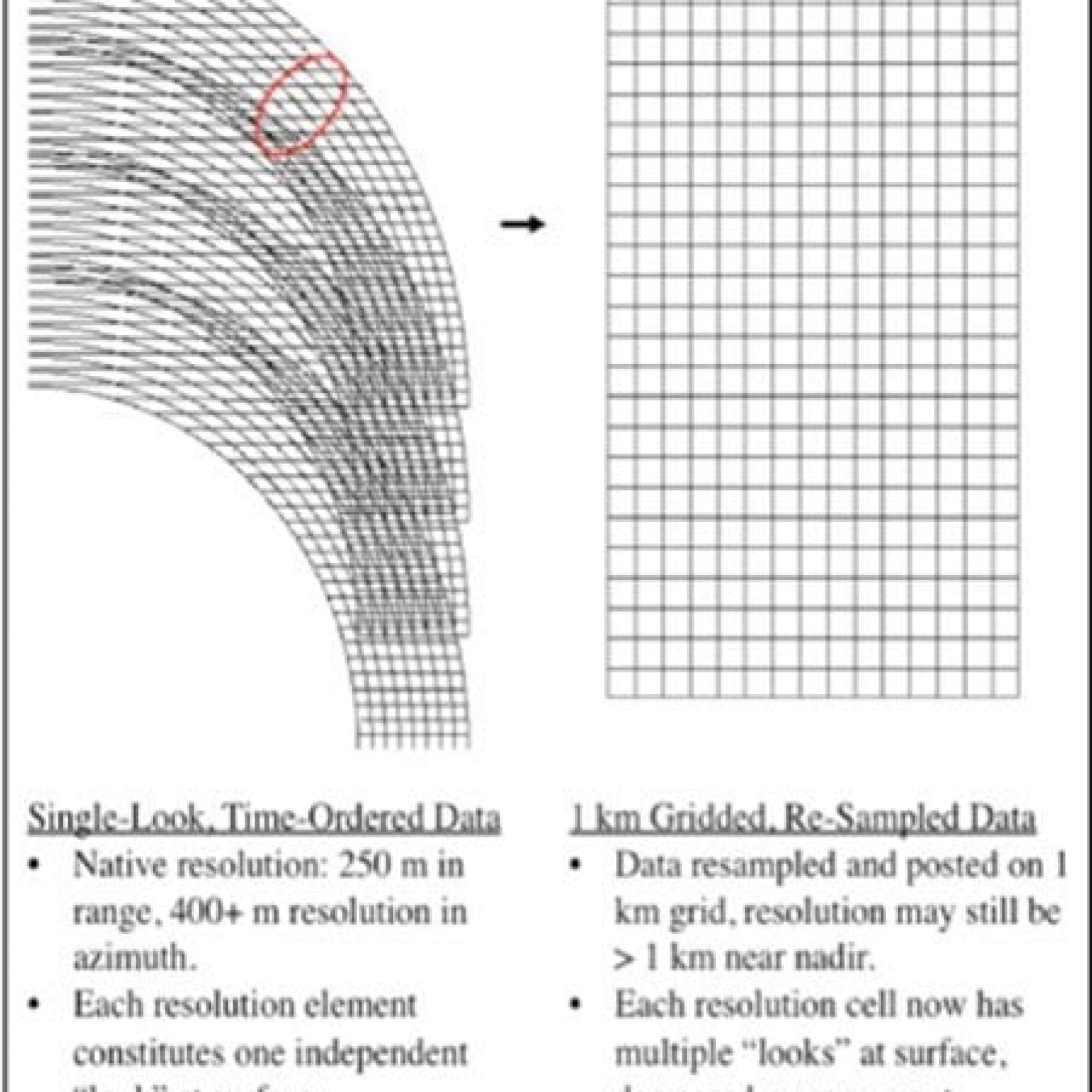
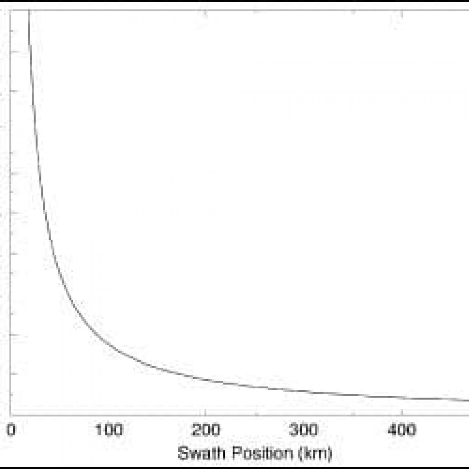
| This panel illustrates the radar-measurement geometry showing the range and Doppler contours. The real aperture radar footprint ellipse is shown at two representative azimuth-scan angles. The radar 1-MHz bandwidth yields a ground-range resolution of ~250 m. The doppler diversity is maximum at a scan angle perpendicular to the satellite velocity (swath edge), leading to an azimuth single-look resolution of ~450 m. The single-look resolution degrades as the scan angles approach the satellite velocity vector. Image Credit: NASA/JPL. | This schematic, which is not drawn to scale, illustrates how the single-look data samples from successive fore-look scans are oriented and overlap relative to the 1-km gred. Image Credit: NASA/JPL. | This panel illustrates the variation as a function of swath position (distance from center track). Image Credit: NASA/JPL. |
Documents
| Name | Description |
|---|---|
| ATBD Documents | Algorithm theoretical basis documents are listed with the products available for download. |
| Product Specification Documents | Product specification documents are listed with the products available for download. |
| ASF SMAP User Guide | For Level 1 products, a streamlined guide to accessing data, using SMAP products, understanding acronyms and abbreviations, and more. |
| Radar Backscatter Calibration, L1B_S0_LoRes and L1C_S0_HiRes Beta Level Data Products | Provides analysis and assessment of calibration quality of SMAP radar normalized backscatter cross-section for the L1B_S0_LoRes and L1C_S0_HiRes beta level data products. Dated 8/5/2015. |
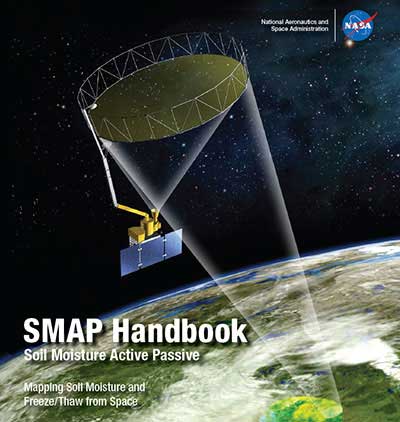
| SMAP Handbook | Written in 2013 as a compendium of information on the project near its time of launch. Contains essential information on programmatic, technological, and scientific aspects of the mission. |
| Ancillary Data Reports (table includes links to cited data) | Application-related descriptions of datasets used with science-algorithm software in generating SMAP science-data products, as well as links to EASE grid information relevant to SMAP products. Also included are links to the ancillary data cited in the reports. |
| Publications | Lists publications on remote sensing of soil moisture since 2001. Please submit additional publications to [email protected], with “SMAP Publications” on the subject line. |
| Worldview quick-look tool | This tool from NASA’s EOSDIS provides the capability to interactively browse global, full-resolution satellite imagery and then download the underlying data. Most of the 100+ available products are updated within three hours of observation. |
| HDF Group | The HDF Group offers a list of software using HDF5. |
| ASF list of potentially useful software tools. |
Tools
| Name | Description |
|---|---|
| ASF Software Tools | ASF offers several tools that can be used on many datasets. |
| SMAP Analysis Client | Interactive application developed by the Jet Propulsion Lab (JPL) / NASA for Soil Moisture Active Passive (SMAP) data. Users may want to start with the calendar icon on the far right of the page. |
| GDAL | The Geospatial Data Abstraction Library helps explore the general contents of SMAP Hierarchical Data Format (HDF) 5 data. The gdalinfo tool summarizes the data structure in the file. The gdal_translate tool can extract the SAR data out of the structure and store it into a more versatile GeoTIFF. |
| ArcGIS (commercial GIS system) | Recognizes the HDF5 structure and is able to extract the SAR data on the fly. Does not calculate standard statistics for this data layer and is slow in rendering the data this way. Can be significantly improved by converting the HDF5 data layer HH into a GeoTIFF file using the gdal_translate tool. |
| HDFView | Provided by the HDF group; looks at data in two ways. For quantitative analysis, the selected data layer must be opened as spreadsheet. For a visual analysis, HDFView provides the image view. The program has no options for stretching data in a statistical fashion. However, the user can manually change the brightness and contrast. |
| Panoply | Developed by NASA’s Goddard Institute for Space Studies, primarily used for global datasets of lower resolution. |
| Interactive Data Language | The Interactive Data Language (IDL) provides a more programmatic means to visualize the SMAP HDF5 data. The IDL H5 browser has very limited functionality in terms of changing visual value ranges and stretching the imagery for visualization purposes, but it does provide users the ability to view the HDF5 products. |
| Worldview quick-look tool | This tool from NASA’s EOSDIS provides the capability to interactively browse global, full-resolution satellite imagery and then download the underlying data. Most of the 100+ available products are updated within three hours of observation. |
| HDF Group | The HDF Group offers a list of software using HDF5. |
| ASF list of potentially useful software tools. |
ASF list of potentially useful software tools.
Acronyms
| Acronym | Definition |
|---|---|
| ASF | Alaska Satellite Facility |
| ATBDs | Algorithm Theoretical Basis Documents |
| Cal/Val | Calibration and Validation |
| DAAC | Distributed Active Archive Center |
| HDF5 | Hierarchical Data Format |
| JPL | Jet Propulsion Laboratory |
| NASA | National Aeronautics and Space Administration |
| NSIDC | National Snow and Ice Data Center |
| ROP | Routine Observations Phase |
| SMAP | Soil Moisture Active Passive |
| SAR | Synthetic Aperture Radar |
| SDS | Science Data System |
| SOP | Science Operations Phase |
| UTC | Coordinated Universal Time |
Publications
Please submit additional relevant publications to [email protected], with “SMAP Publications” on the subject line.
| Publication Year | Document title and download link (if available) |
|---|---|
| 2014 | Assessment of Soil Moisture Data Requirements by the Potential SMAP Data User Community: Review of SMAP Mission User Community – M.E. Brown, V.M. Escobar; Selected Topics in Applied Earth Observations and Remote Sensing, IEEE Journal of, Vol. 7 No. 1, Jan. 2014, p.277-283, doi: 10.1109/JSTARS.2013.2261473. |
| 2014 | Automated L-Band Radar System for Sensing Soil Moisture at High Temporal Resolution– K. Nagarajan, Pang-Wei Liu, R. DeRoo, J. Judge, R. Akbar, P. Rush, S. Feagle, D. Preston, R. Terwilleger; Geoscience and Remote Sensing Letters, IEEE, Vol. 11 No. 2, 2014, p. 504-508, doi: 10.1109/LGRS.2013.2270453 |
| 2014 | The Soil Moisture Active Passive Experiments (SMAPEx): Toward Soil Moisture Retrieval From the SMAP Mission – R. Panciera, J.P. Walker, T.J. Jackson, D.A. Gray, M.A. Tanase, Dongryeol Ryu, A. Monerris, H. Yardley, C. Rudiger, Xiaoling Wu, Ying Gao, J.M. Hacker; Geoscience and Remote Sensing, IEEE Transactions on, Vol. 52 No. 1, Part 2, 2014, p. 490-507, doi: 10.1109/TGRS.2013.2241774 |
| 2014 | Tests of the SMAP Combined Radar and Radiometer Algorithm Using Airborne Field Campaign Observations and Simulated Data – N.N. Das, D. Entekhabi, E.G. Njoku, J.J.C. Shi, J.T. Johnson, A. Colliander; Geoscience and Remote Sensing, IEEE Transactions on, Vol. 52 No.4, 2014, p. 2018-2028, doi: 10.1109/TGRS.2013.2257606 |
| 2013 | A downscaling algorithm for combining radar and radiometer observations for SMAP soil moisture retrieval – Peng Guo, Jiancheng Shi, Tianjie Zhao; Geoscience and Remote Sensing Symposium (IGARSS), 2013 IEEE International, p. 731 – 734, doi: 10.1109/IGARSS.2013.6721261 |
| 2013 | L-band active / passive time series measurements over a growing season using the ComRAD ground-based SMAP simulator – P. O’Neill, M. Kurum, A. Joseph, J. Fuchs, P. Young, M. Cosh, R. Lang; Geoscience and Remote Sensing Symposium (IGARSS), 2013 IEEE International, p. 37-40, doi: 10.1109/IGARSS.2013.6721086 |
| 2013 | NASA’s Soil Moisture Active Passive (SMAP) observatory – K. Kellogg, K., et al.; Aerospace Conference, 2013 IEEE, p. 1-20, doi: 10.1109/AERO.2013.6496938 |
| 2013 | Performance characterization of the SMAP RFI mitigation algorithm using direct-sampled SMAPVEX 2012 data – S. Misra, J. Johnson, M. Aksoy, D. Bradley, Hsin Li, J. Mederios, J. Piepmeier, I. O’Dwyer; Radio Science Meeting (USNC-URSI NRSM), 2013 US National Committee of URSI National, p. 1, doi: 10.1109/USNC-URSI NRSM.2013.6524988 |
| 2013 | A radar-radiometer surface soil moisture retrieval algorithm for SMAP, – R. Akbar, M. Moghaddam; Geoscience and Remote Sensing Symposium (IGARSS), 2013 IEEE International, p. 1095-1098, doi: 10.1109/IGARSS.2013.6721355 |
| 2013 | A robust algorithm for soil moisture retrieval from the soil Moisture Active Passive mission radar observations – P.S. Narvekar, D. Entekhabi, Seungbum Kim, E. Njoku; Geoscience and Remote Sensing Symposium (IGARSS), 2013 IEEE International, p. 45-48, doi: 10.1109/IGARSS.2013.6721088 |
| 2013 | SMAP RFI mitigation algorithm performance characterization using airborne high-rate direct-sampled SMAPVEX 2012 data – S. Misra, et al.; Geoscience and Remote Sensing Symposium (IGARSS), 2013 IEEE International, p. 41 – 44, doi: 10.1109/IGARSS.2013.6721087 |
| 2013 | The Soil Moisture Active Passive (SMAP) radar: Measurements at high latitudes and of surface freeze/thaw state – M. Spencer, S. Dunbar, C. Chen; Radar Conference (RADAR), 2013 IEEE, p. 1-5, doi: 10.1109/RADAR.2013.6586087 |
| 2013 | State of the Art in Large-Scale Soil Moisture Monitoring – Tyson E. Ochsner, Michael H. Coshb, Richard H. Cuencac, Wouter A. Dorigod, Clara S. Drapere, Yutaka Hagimotof, Yann H. Kerrg, Eni G. Njokuh, Eric E. Smalli and Marek Zredaj; Soil Science Society of America Journal, Vol. 77 No. 6, p. 1888-1919; doi:10.2136/sssaj2013.03.0093. |
| 2013 | Towards a high-density soil moisture network for the validation of SMAP in Petzenkirchen, Austria – M. Vreugdenhil, et al.; Geoscience and Remote Sensing Symposium (IGARSS), 2013 IEEE International, p. 1865 – 1868, doi: 10.1109/IGARSS.2013.6723166 |
| 2013 | US national cropland soil moisture monitoring using SMAP – Zhengwei Yang, R. Mueller, W. Crow; Geoscience and Remote Sensing Symposium (IGARSS), 2013 IEEE International, p. 3746 – 3749, doi: 10.1109/IGARSS.2013.6723645 |
| 2012 | Advances in Earth observation for water cycle science (editorial) – D. Fernandez-Prieto et al., Copernicus Publications on behalf of the European Geosciences Union, Hydrol. Earth Syst. Sci., 16, p. 543–549, 2012, doi:10.5194/hess-16-543-2012 |
| 2012 | Active and passive airborne microwave remote sensing for soil moisture retrieval in the Rur catchment, Germany – C. Montzka, et al., Geoscience and Remote Sensing Symposium (IGARSS), 2012 IEEE International, p. 6956 – 6959, doi: 10.1109/IGARSS.2012.6352562 |
| 2012 | An airborne simulation of the SMAP data stream – J.P. Walker et al.; Geoscience and Remote Sensing Symposium (IGARSS), 2012 IEEE International, p. 5-7 doi: 10.1109/IGARSS.2012.6351537 |
| 2012 | Application of QuikSCAT Backscatter to SMAP Validation Planning: Freeze/Thaw State Over ALECTRA Sites in Alaska From 2000 to 2007 – A. Colliander, K. McDonald, R. Zimmermann, R. Schroeder, J.S. Kimball, E.G. Njoku; Geoscience and Remote Sensing, IEEE Transactions on, Vol. 50 No. 2, 2012, p. 461 – 468 , doi: 10.1109/TGRS.2011.2174368 |
| 2012 | Assessment of the impacts of radio frequency interference on SMAP radar and radiometer measurements – C.W. Chen, J.R. Piepmeier, J.T. Johnson, H. Ghaemi, H.; Geoscience and Remote Sensing Symposium (IGARSS), 2012 IEEE International, p. 1-4, doi: 10.1109/IGARSS.2012.6351538 |
| 2012 | Comparison of Backscattering Models at L-Band for Growing Corn – A. Monsivais-Huertero, J. Judge, Geoscience and Remote Sensing Letters, IEEE, Vol. 8 No. 1, p. 24-28, doi: 10.1109/LGRS.2010.2050459 |
| 2012 | Design and performance of Astromesh reflector onboard Soil Moisture Active Passive spacecraft – M. Mobrem, et al.; Aerospace Conference, 2012 IEEE, p. 1-10, doi: 10.1109/AERO.2012.6187094 |
| 2012 | Development of SMAP (soil moisture active and passive) Freeze/Thaw algorithms adapted for the Canadian Tundra – P. Kalantari, M. Bernier, K.C. McDonald, J. Poulin; Geoscience and Remote Sensing Symposium (IGARSS), 2012 IEEE International, p. 5218 – 5221, doi: 10.1109/IGARSS.2012.6352433 |
| 2012 | A dual-polarized, dual-frequency, corrugated feed horn for SMAP – P. Focardi, P.R. Brown, Antennas and Propagation Society International Symposium (APSURSI), 2012 IEEE, p. 1-2, doi: 10.1109/APS.2012.6349003 |
| 2012 | End-to-end data flow on the Soil Moisture Active Passive (SMAP) mission – E. Deems, C. Swan, B. Weiss; Aerospace Conference, 2012 IEEE, p. 1-16, doi: 10.1109/AERO.2012.6187175 |
| 2012 | An integrated active-passive soil moisture retrieval algorithm for SMAP for bare surfaces – R. Akbar, M. Moghaddam; Geoscience and Remote Sensing Symposium (IGARSS), 2012 IEEE International, p. 16 – 19, doi: 10.1109/IGARSS.2012.6350891 |
| 2012 | Integration of Daily Inundation Extent Estimates into an Ecosystem-Atmosphere Gas Exchange Model – J. Galantowicz, A. Samanta, H. Tian, American Geophysical Union, Fall Meeting 2012, abstract #B41C-0303 |
| 2011 | A 6-m mesh reflector antenna for SMAP: Modeling the RF performance of a challenging Earth-orbiting instrument – P. Focardi, P. Brown, Y. Rahmat-Samii; Antennas and Propagation (APSURSI), 2011 IEEE International Symposium on, p. 2987- 2990, doi: 10.1109/APS.2011.5997157 |
| 2011 | AIAA ICES 2011 – Preliminary Evaluation of Passive Thermal Control for the Soil Moisture Active Passive (SMAP) Radiometer – A.J. Mastropietro, Eug Kwack, Rebecca Mikhaylov, Michael Spencer, Pamela Hoffman, Douglas Dawson (JPL); Jeff Piepmeier, Derek Hudson, James Medeiros (GSFC). Download File |
| 2011 | An Algorithm for Merging SMAP Radiometer and Radar Data for High-Resolution Soil-Moisture Retrieval – Narendra N. Das, Dara Entekhabi, Eni G. Njoku, IEEE Transactions on Geoscience and Remote Sensing, Vol. 49, No. 5, May 2011. |
| 2011 | Dense Temporal Series of C- and L-band SAR Data for Soil Moisture Retrieval Over Agricultural Crops – Anna Balenzano, Francesco Mattia, Senior Member, IEEE, Giuseppe Satalino, and Malcolm W. J. Davidson, IEEE Transactions on Geoscience and Remote Sensing, Vol. 4, No. 2, June 2011. |
| 2011 | Effect of Soil Moisture on polarimetric-interferometric repeat pass observations by UAVSAR during 2010 Canadian Soil Moisture campaign – Scott Hensley, Thierry Michel, Jakob Van Zyl, Ron Muellerschoen, Bruce Chapman, Shadi Oveisgharan, Ziad S. Haddad,Tom Jackson, Iliana Mladenova, SMAP Cal/Val Workshop, May 3-5, 2011. |
| 2011 | IGARSS 2011 – Utilization of Ancillary Data Sets for SMAP Algorithm Development and Product Generation; Peggy E. O’Neill, Erika Podest, and Eni G. Njoku. |
| 2011 | Improving hydrologic predictions of a catchment model via assimilation of surface soil moisture – Chen, F., W.T. Crow, P.J. Starks, and D.N. Moriasi, Advances in Water Resources, 34, 526–536, 2011. Download File |
| 2010 | A quasi-global evaluation system for satellite-based surface soil moisture retrievals – Crow, W.T., D.G. Miralles and M.H. Cosh, IEEE Transactions on Geoscience and Remote Sensing, 48(6), 2516-2527. Download File |
| 2010 | A technique for estimating spatial sampling errors in coarse-scale soil moisture estimates derived from point-scale observations – Miralles, D.G., W.T. Crow and M.H. Cosh, Journal of Hydrometeorology, 11(6), 1404-1410,10.1175/2010JHM1285.1, 2010. Download File |
| 2010 | AGU 2010 – The Contribution of Soil Moisture Information to Forecast Skill: Two Studies; Randal Koster, Sarith Mahanama, and Ben Livneh. |
| 2010 | AMS 2010 – NASA’s Soil Moisture Active Passive (SMAP) Mission Applications in the Atmospheric and Hydrologic Sciences; Dara Entekhabi, Eni Njoku, Peggy O’Neill, R. Koster. |
| 2010 | An algorithm for merging SMAP radiometer and radar data for high resolution soil moisture retrieval – Das, N., Entekhabi, D., Njoku, E., IEEE-Transactions on Geoscience and Remote Sensing, In press. |
| 2010 | An improved approach for estimating observation and model error parameters for soil moisture data assimilation – Crow, W.T. and M.J. van den Berg, Water Resources Research, 46, W12519, 10.1029/2010WR009402, 2010. Download File |
| 2010 | Assimilation of SMAP measurements for soil moisture-based military trafficability assessment at tactical scales – Flores, L., D. Entekhabi, and R. L. Bras, IEEE Journal of Selected Topics in Earth Observations and Remote Sensing, 2009-00030. |
| 2010 | Backscattering coefficients, coherent reflectivities, and emissivities of randomly rough soil surfaces at L-band for SMAP applications based on numerical solutions of Maxwell equations in three-dimensional simulations – Huang, Shaowu, Tsang, Leung, Njoku, Eni and Chan, Kuan Shan, IEEE Transactions of Geoscience and Remote Sensing, Vol. 48, No. 6, June 2010, 2557-2568. Download File |
| 2010 | Evaluating the utility of remotely-sensed soil moisture retrievals for operational agricultural drought monitoring – Bolten, J.D., W.T. Crow, T.J. Jackson, X. Zhan and C.A. Reynolds. IEEE Journal of Selected Topics in Applied Earth Observations and Remote Sensing, 3, 57-66. Download File |
| 2010 | IGARSS 2010 – Forward Simulation of Passive Microwave Observation for the Soil Moisture Active Passive (SMAP) Mission; Steven Chan, Eni Njoku, and Scott Dunbar. |
| 2010 | IGARSS 2010 – Fostering Applications opportunities for the NASA Soil Moisture Active Passive (SMAP) Mission; M. Susan Moran, Peggy E. O’Neill, Dara Entekhabi, Eni Njoku and Kent Kellogg. |
| 2010 | IGARSS 2010 – QuikSCAT Backscatter Sensitivity to Landscape Freeze/Thaw State over ALECTRA Sites in Alaska from 2000 to 2007: Application to SMAP Validation Planning; A. Colliander, K. McDonald, R. Zimmermann, T. Linke, R. Schroeder, J. Kimball. |
| 2010 | IGARSS 2010 – The NASA Soil Moisture Active Passive (SMAP) Mission: Overview; O’Neil, Entekhabi, Njoku and Kellogg. |
| 2010 | The impact of radar incidence angle on soil moisture retrieval skill – Crow, W.T., W. Wagner and V. Naeimi, IEEE Geoscience and Remote Sensing Letters, 7(3), 501-505, 10.1109/LGRS.2010.2040134, July 2010. Download File |
| 2010 | MicroRad 2010 – Utilization of Airborne and In Situ Data Obtained in SGP99, SMEX02, CLASIC and SMAPVEX08 Field Campaigns for SMAP Soil Moisture Algorithm Development and Validation; Colliander, A., S. Chan, S. Yueh, M. Cosh, R. Bindlish, T. Jackson, E. Njoku. |
| 2010 | PIEEE 2010 – The Soil Moisture Active and Passive (SMAP) Mission, Entekhabi, D., E. Njoku, P. O’Neill, K. Kellogg, W. Crow, W. Edelstein, J. Entin, S. Goodman, T. Jackson, J. Johnson, J. Kimball, J. Piepmeier, R. Koster, K. McDonald, M. Moghaddam, S. Moran, R. Reichle, J. C. Shi, M. Spencer, S. Thurman, L. Tsang, J. Van Zyl, Proceedings of the IEEE, 98(5). |
| 2010 | PIERS 2010 – Azimuthal Signature of Coincidental Brightness Temperature and Normalized Radar Cross-section Obtained Using Airborne PALS Instrument; Colliander, A., S. Kim, S. Yueh, M. Cosh, T. Jackson, E. Njoku. |
| 2010 | RadarCon 2010 – Monitoring surface soil moisture and freeze-thaw state with the high-resolution radar of the Soil Moisture Active/Passive (SMAP) mission; Kim, S, Van Zyl J, McDonald, K. and Njoku, E. |
| 2010 | Soil Moisture Active Passive Poster – Joshua B. Fisher, Eni G. Njoku, Data Entekhabi. |
| 2010 | Study of validity region of small perturbation method for two-layer rough surfaces – Tabatabaeenejad, A., and M. Moghaddam, IEEE Geosci. Remote Sensing Lett, vol. 7, no. 2, pp. 319-323, April 2010. |
| 2009 | 2009 IEEE Radar Conference – A Science Data System Approach For The SMAP Mission; Woollard D, Kwoun OI, Bicknell T, et al., Pages: 664-669 MAY 2009. |
| 2009 | 2009 IEEE Radar Conference – RFI STUDY FOR THE SMAP RADAR; Chan S, Spencer M, Pages: 143-147 MAY 2009. |
| 2009 | 2009 IEEE Radar Conference – SMAP’s Radar OBP Algorithm Development ; Le C, Spencer MW, Veilleux L, et al., Pages 660-663 MAY 2009. |
| 2009 | AIAA 2009 – The Soil Moisture Active and Passive Mission (SMAP), Njoku, E., K. Kellogg, P. O’Neill, and D. Entekhabi. |
| 2009 | A Change Detection Algorithm for Retrieving High-Resolution Soil Moisture From SMAP Radar and Radiometer Observations – Piles M, Entekhabi D, Camps A, IEEE TRANSACTIONS ON GEOSCIENCE AND REMOTE SENSING Volume: 47 Issue: 12 Pages: 4125-4131 DEC 2009. |
| 2009 | AGU 2009, Fall – Development of Global High Resolution Soil Moisture Product from the SMAP mission; Narendra N. Das, Dara Entekhabi, Eni Njoku. |
| 2009 | A Satellite Approach to Estimate Land-Atmosphere CO2 Exchange for Boreal and Arctic Biomes Using MODIS and AMSR_E – John Kimball, Lucas Jones, Ke Zhang, Faith Ann Heinsch, Kyle McDonald and Walt Oechel, IEEE Transactions on Geoscience and Remote Sensing, Vol 47, No.2, February 2009. Download File |
| 2009 | A study of detection algorithms for pulsed sinusoidal interference in microwave radiometry – J. T. Johnson and L. C. Potter, IEEE Trans. Geosc. Rem. Sens., vol. 47, pp. 628–636, 2009. |
| 2009 | Combined Passive and Active Microwave Observations of Soil Moisture During CLASIC – Bindlish, R; Jackson, T; Sun, RJ; et al., IEEE GEOSCIENCE AND REMOTE SENSING LETTERS, 6 (4): 644-648 OCT 2009. |
| 2009 | Ecohydrological controls on snowmelt partitioning in mixed-conifer sub-alpine forests – Noah.P. Molotch, Paul D. Brooks, Sean P. Burns, Marcy Litvak, Russell K. Monson, Jospeh R. McConnell, and Keith Musselman, Echodydrology. 2, 129-142 (2009) DOI: 10.1002/eco.48. Download File |
| 2009 | IEEE Radar Conference – The Soil Moisture Active and Passive Mission (SMAP): Science and Applications; Entekhabi, D; O’Neill, P; Njoku, E, 83-85 2009. |
| 2009 | IEEE Radar Conference 2009 – Soil Moisture Active and Passive Mission, Entekhabi, D., E. Njoku and P. O’Neill. |
| 2009 | IGARSS 2009 – A change detection algorithm for retrieving high-resolution surface soil moisture from SMAP L-band radar and radiometer observations, Piles, M., D. Entekhabi and A. Camps. |
| 2009 | IGARSS 2009 – Airborne L-band RFI observations in the SMAPVEX08 Campaign with the L-band Interference Suppressing Radiometer; Majurec, N., J. Park, N. Niamsuwan, M. Frankford, and J. T. Johnson. |
| 2009 | IGARSS 2009 – Algorithm development using the SMAP Algorithm Testbed, Chan, S., S. Dunbar, A. Colliander, E. Njoku and D. Entekhabi. |
| 2009 | IGARSS 2009 – High Resolution Mapping of Soil Moisture with SMAP Radar and Radiometer in Support of new Approaches to Water Cycle Science and Applications; Entekhabi et al. |
| 2009 | IGARSS 2009 – PALS-ADD and airborne campaigns to support soil moisture and sea surface salinity missions; Yueh, S. et al. |
| 2009 | IGARSS 2009 – Space-borne soil moisture measurements in support of flood hydrology: The NASA SMAP approach; Crow et al. |
| 2009 | Impact of hillslope-scale organization of topography, soil moisture, soil temperature and vegetation on modeling surface microwave radiation emission, Flores, A. N., V. Y. Ivanov, D. Entekhabi, and R. L. Bras, IEEE Transactions of Geoscience and Remote Sensing, 47(8), 2557-2571. |
| 2009 | Improving satellite rainfall accumulation estimates using spaceborne soil moisture retrievals – Crow, W.T., G.F. Huffman, R. Bindlish and T.J. Jackson, Journal of Hydrometeorology, 10(1), 199-212. Download File |
| 2009 | Inversion of dielectric properties of layered rough surface using the simulated annealing method – Tabatabaeenejad, A., and M. Moghaddam, IEEE Trans. Geosci. Remote Sensing, vol. 47, no. 7, pp. 2035-2046, July 2009. |
| 2009 | L-Band Radar Estimation of Forest Attenuation for Active/Passive Soil Moisture Inversion – Kurum, M; Lang, RH; O’Neill, PE; et al., IEEE TRANSACTIONS ON GEOSCIENCE AND REMOTE SENSING, 47 (9): 3026-3040 Sp. Iss. SI SEP 2009. |
| 2009 | PIERS 2009 – Retrieval Algorithm Development Based on SMEX02 Field Campaign Data for the Soil Moisture Active and Passive (SMAP) Mission; Chan and Njoku. |
| 2009 | PIERS 2009 – Soil Moisture Active and Passive (SMAP) Mission; Entekhabi et al. |
| 2009 | Role of subsurface physics in the assimilation of surface soil moisture observations – Kumar, S. V., R. H. Reichle, R. D. Koster, W. T. Crow, and C. D. Peters-Lidard, Journal of Hydrometeorology, 10, 1534-1547; http://dx.doi.org/10.1175/2009JHM1134.1. |
| 2009 | Survey of L-Band tower and airborne sensor systems relevant to upcoming soil moisture missions, O’Neill, P., T. Jackson, D. Entekhabi and E. Njoku , IEEE Geoscience and Remote Sensing Newsletter, 151, 13-16. |
| 2009 | URSI National Radio Science Meeting 2009 – Airborne L-band radio frequency interference studies with the L-band Interference Suppressing Radiometer (LISR) and PALS; Park, J., N. Majurec, N. Niamsuwan, M. Frankford, J. T. Johnson, S. Dinardo, S. Yueh. |
| 2008 | 2008 IEEE Radar Conference – THE SOIL MOISTURE ACTIVE/PASSIVE (SMAP) RADAR; Spencer, M; Kim, Y; Chan, S, 931-935 2008. |
| 2008 | 2008 MICROWAVE RADIOMETRY AND REMOTE SENSING OF THE ENVIRONMENT – Estimation of Canopy Attenuation for Active/Passive Microwave Soil Moisture Retrieval Algorithms; Kurum, M; Lang, RH; O’Neill, PE; et al., : 136-139 2008. |
| 2008 | An adaptive ensemble Kalman filter for soil moisture data assimilation – Reichle, R. H., W. T. Crow, and C. L. Keppenne, Water Resources Research, 44, W03423, http://dx.doi.org/10.1029/2007WR006357. |
| 2008 | Contribution of soil moisture retrievals to land data assimilation products – Reichle, R. H., W. T. Crow, R. D. Koster, H. Sharif, and S. P. P. Mahanama, Geophysical Research Letters, 35, L01404, http://dx.doi.org/10.1029/2007GL031986. |
| 2008 | IGARSS 2008 – Active-passive observations of soil moisture – Implementation concept for the SMAP mission, Njoku, E., D. Entekhabi, and P. O’Neill. |
| 2008 | IGARSS 2008 – Hillslope-scale controls on remote sensing of soil moisture with microwave radiometry, Flores, A. V. Ivanov, D. Entekhabi, and R. Bras. |
| 2008 | IGARSS 2008 – THE SOIL MOISTURE ACTIVE/PASSIVE MISSION (SMAP); Entekhabi et al. |
| 2008 | PROCEEDINGS OF THE SOCIETY OF PHOTO-OPTICAL INSTRUMENTATION ENGINEERS (SPIE) – Soil Moisture Active/Passive (SMAP) Mission Concept; Entekhabi, D; Jackson, TJ; Njoku, E; et al., art. no. 70850H, 7085: H850-H850 2008. |
| 2008 | SPIE 2008 – Soil Moisture Active/Passive (SMAP) Mission Concept; T. J. Jackson, D. Entekhabi, E. Njoku, P. O’Neill, and J. Entin. |
| 2007 | Comparison and assimilation of global soil moisture retrievals from the Advanced Microwave Scanning Radiometer for the Earth Observing System (AMSR-E) and the Scanning Multichannel Microwave Radiometer (SMMR) – Reichle, R. H., R. D. Koster, P. Liu, S. P. P. Mahanama, E. G. Njoku, and M. Owe, Journal of Geophysical Research – Atmospheres, 112, D09108, http://dx.doi.org/10.1029/2004GL021700. |
| 2007 | Fall AGU 2007 – Soil Moisture Active Passive (SMAP) Mission; Dara Entekhabi, Eni Njoku, Peggy O’Neill,T.J. Jackson, S.W. Boland, J.K. Entin, E. Im. |
| 2007 | IGARSS 2007 – Algorithm for High-Resolution Soil Moisture Retrieval With Coincident Active and Passive L-Band Measurements; Dara Entekhabi. |
| 2007 | Impact of multiresolution active and passive microwave measurements on soil moisture estimation using the ensemble Kalman smoother – Dunne, SC; Entekhabi, D; Njoku, EG, IEEE TRANSACTIONS ON GEOSCIENCE AND REMOTE SENSING, 45 (4): 1016-1028 APR 2007. |
| 2006 | A Method for Retrieving High Resolution Surface Soil Moisture from Hydros L-Band Radiometer and Radar Observations – Zhan, X., Houser, P. R., Walker , J. P. and Crow, W., IEEE Transactions on Geoscience and Remote Sensing, 44(6):1534-1544, 2006, doi:10.1109/TGRS.2005.863319. |
| 2006 | 2006 IEEE MicroRad – L-band active and passive sensing of soil moisture through forests; Lang, RH, Chauhan, N; Utku, C; et al., : 193-196 2006. |
| 2005 | Global assimilation of satellite surface soil moisture retrievals into the NASA Catchment land surface model – Reichle, R. H. and R. D. Koster, Geophysical Research Letters, 32, L02404, http://dx.doi.org/10.1029/2004GL021700. |
| 2005 | Relevance of time-varying and time-invariant retrieval error sources on the utility of spaceborne soil moisture products – Crow, W.T., Koster, R., Reichle, R., Sharif, H., Geophysical Research letters, Vol. 32, L24405, doi: 1029/2005GL024889, 2005. Download File |
| 2004 | Bias reduction in short records of satellite soil moisture – Reichle, R. H. and R. D. Koster, Geophysical Research Letters, 31, L19501 http://dx.doi.org/10.1029/2004GL020938. |
| 2004 | Global Soil Moisture from Satellite Observations, Land Surface Models, and Ground Data: Implications for Data Assimilation – Reichle, R. H., R. D. Koster, J. Dong, and A. A. Berg Journal of Hydrometeorology, 5, 430-442, 2004. |
| 2004 | IEEE International Symposium on Geoscience and Remote Sensing (IGARSS) – Combination of passive and active microwave data for soil moisture estimates; Ghedira, H; Lakhankar, T; Jahan, N; et al., : 2783-2786 2004. |
| 2004 | Retrieval of soil moisture from passive and active L/S band sensor (PALS) observations during the Soil Moisture Experiment in 2002 (SMEX02) – Narayan, U; Lakshmi, V; Njoku, EG, REMOTE SENSING OF ENVIRONMENT, 92 (4): 483-496 SEP 30 2004. |
| 2003 | IEEE International Symposium on Geoscience and Remote Sensing (IGARSS) – An algorithm to retrieve soil moisture using synergistic active/passive microwave, data on bare soil surface; Zhang, WG; Chao, W; Hong, Z; et al., : 917-919 2003. |
| 2003 | IEEE International Symposium on Geoscience and Remote Sensing (IGARSS) – Soil moisture retrieval through changing corn using active passive microwave remote sensing; O’Neill, PE; Joseph, A; De Lannoy, G; et al., : 407-409 2003. |
| 2003 | Soil moisture retrieval using the passive/active L- and S-band radar/radiometer – Bolton, JD; Lakshmi, V; Njoku, EG, IEEE TRANSACTIONS ON GEOSCIENCE AND REMOTE SENSING, 41 (12): 2792-2801 Part 1 DEC 2003. |
| 2002 | IEEE International Symposium on Geoscience and Remote Sensing (IGARSS) – Measuring soil moisture change with vegetation cover using passive and active microwave data; Li, Z; Shi, JC; Guo, HD, : 3071-3073 2002. |
| 2001 | Passive active L- and S-band (PALS) microwave sensor for ocean salinity and soil moisture measurements – Wilson, WJ; Yueh, SH; Dinardo, SJ; et al., IEEE TRANSACTIONS ON GEOSCIENCE AND REMOTE SENSING, 39 (5): 1039-1048 MAY 2001. |
Passive active L- and S-band (PALS) microwave sensor for ocean salinity and soil moisture measurements – Wilson, WJ; Yueh, SH; Dinardo, SJ; et al., IEEE TRANSACTIONS ON GEOSCIENCE AND REMOTE SENSING, 39 (5): 1039-1048 MAY 2001.
Credits
SMAP Team
Soil Moisture Active Passive (SMAP) is a directed mission within the NASA Earth Systematic Mission Program. The SMAP project is managed by the Jet Propulsion Laboratory (JPL) with participation by the Goddard Space Flight Center (GSFC).
JPL is responsible for project management, system engineering, instrument management, the radar instrument, mission operations and the ground data system, science-data processing, and delivery of science-data products to a designated archive for public distribution.
GSFC is responsible for the radiometer instrument, science-data processing, and delivery of science-data products to a designated archive for public distribution.
ASF and the National Snow and Ice Data Center (NSIDC) are responsible for distributing data to the public.
Key Program/Project Personnel
C. Bonniksen (NASA/Hq), Program Executive, NASA HQ
J. Entin (NASA/Hq), Program Scientist, NASA HQ
K. Kellogg (JPL), Project Manager, JPL
S. Yueh (JPL), Project Scientist, JPL
P. ONeill (GSFC), Deputy Project Scientist, GSFC
Science Team
The SMAP Science Team (ST) was selected competitively by NASA in 2013 through a ROSES proposal solicitation. ST members are responsible for advising the project on science requirements, science-product definition, science algorithms, calibration/validation planning and implementation, and for publishing science results and supporting education and public outreach for the project. The ST replaces the earlier Science Definition Team (SDT), whose tenure ended in 2013. The ST tenure extends through the end of the SMAP mission.
Science Team Leader
D. Entekhabi, Massachusetts Institute of Technology
U.S. ST Members:
W. Crow, U.S. Department of Agriculture
T. Jackson, U.S. Department of Agriculture
J. Johnson, Ohio State University
J. Kimball, University of Montana
R. Koster, NASA Goddard Space Flight Center
D. Le Vine, NASA Goddard Space Flight Center
S. Misra, Jet Propulsion Laboratory
M. Moghaddam, University of Southern California
S. Moran, U.S. Department of Agriculture
R. Reichle, NASA Goddard Space Flight Center
K. Sarabandi, University of Michigan
L. Tsang, University of Washington
J. van Zyl, Jet Propulsion Laboratory
E. Wood, Princeton University
International ST Members:
S. Belair, Environment Canada, Canada
R. Gurney, University of Reading, UK
Y. Kerr, CESBIO, France
N. Pierdicca, University of Rome, Italy
J. Walker, Monash University, Clayton, Australia
Applications Coordinator:
M. Brown, NASA Goddard Space Flight Center
Site Content
Adapted from JPL SMAP website.
SMAP products are processed at Levels 1, 2, 3, and 4. ASF distributes Level 1 radar products. See the Instrument events timetable
The SMAP baseline science-data products are publicly available through two NASA-designated data centers, the Alaska Satellite Facility (ASF) and the National Snow and Ice Data Center (NSIDC) DAAC. ASF will distribute the Level 1 radar products and NSIDC will distribute the radiometer and Level 2-4 products. All products will conform to the HDF-5 standard.
SMAP synthetic aperture radar (SAR) data have a spatial resolution of 1-3 km over the outer 70% of the swath (L1C_S0_HiRes product). The low-resolution radar data are ‘slices’ of resolution approximately 5 km x 30 km (L1B_S0_LoRes product). The radiometer data have a spatial resolution (IFOV) of 39 km x 47 km, nominally referred to as 40-km resolution (L1B_TB product). The L1C_TB data products are resampled TB data on a 36-km Earth grid and will have spatial resolution ~10% greater than the L1B_TB data (depending on the resampling method).
SMAP science-data products will be generated on the Science-Data System production system using science software developed on the SDS Testbed. The science software is based on algorithms for each product described in the Algorithm Theoretical Basis Documents (ATBDs).
| Short Name | Description | Gridding (km) | Latency* | ATBD** | Product Spec Doc | Source |
|---|---|---|---|---|---|---|
| L1A_Radar | Raw radar data in time order (half orbit) | – | 12 hrs | n/a | View | ASF |
| L1A_Radiometer | Radiometer raw data in time order | – | 12 hrs | n/a | NSIDC | |
| L1B_S0_LoRes | Low-resolution radar σ ο in time order (half orbit) | 5×30 | 12 hrs | View | View | ASF |
| Backscatter analysis document | ||||||
| L1B_TB | Radiometer TB in time order | 36×47 | 12 hrs | View | NSIDC | |
| L1C_S0_HiRes | High-resolution radar σ ο (half orbit gridded) | 1 | 12 hrs | View | View | ASF |
| Backscatter analysis document | (1-3)*** | |||||
| L1C_TB | Radiometer T B (half orbit, gridded) | 36 | 12 hrs | View | NSIDC | |
| L2_SM_A | Soil moisture (radar, half orbit) | 3 | 24 hrs | View | NSIDC | |
| L2_SM_P | Soil moisture (radiometer, half orbit) | 36 | 24 hrs | View | NSIDC | |
| L2_SM_A/P | Soil moisture (radar/radiometer, half orbit) | 9 | 24 hrs | View | NSIDC | |
| L3_F/T_A | Freeze-thaw state (radar, daily composite) | 3 | 50 hrs | View | NSIDC | |
| L3_SM_A | Soil moisture (radar, daily composite) | 3 | 50 hrs | View | NSIDC | |
| L3_SM_P | Soil moisture (radiometer, daily composite) | 36 | 50 hrs | View | NSIDC | |
| L3_SM_A/P | Soil moisture (radar/radiometer, daily composite) | 9 | 50 hrs | View | NSIDC | |
| L4_SM | Soil moisture (surface and root zone) | 9 | 7 days | View | NSIDC | |
| L4_C | Carbon net ecosystem exchange (NEE) | 9 | 14 days | View | NSIDC |
*Mean latency under normal operating conditions (defined as time from data acquisition by the observatory to availability to the public data archive).
**Algorithm Theoretical Basis Documents (ATBDs) provide the physical and mathematical descriptions of the algorithms used in the generation of science-data products. The ATBDs include a description of variance and uncertainty estimates and considerations of calibration and validation, exception control, and diagnostics. Internal and external data flows are also described.
***Over outer 70% of swath
Ancillary Data Reports
The SMAP Ancillary Data Reports below hold application-related descriptions of datasets used with science-algorithm software in generating SMAP science-data products, as well as links to EASE grid information relevant to SMAP products.
These reports may undergo additional updates as new ancillary datasets or processing methods become available.
| Data Reports | Ancillary Data Examples | Main Ancillary Data Cited |
|---|---|---|
| Crop Type | 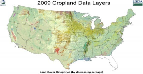 | USDA Cropland Data ECOCLIMAP (global database of land surface parameters) |
| Landcover | 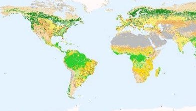 | MODIS Land Cover Type (NASA Moderate Resolution Imaging Spectroradiometer) |
| Digital Elevation Model | 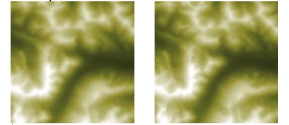 | JPL Global Digital Elevation Model |
| Soil Attributes | 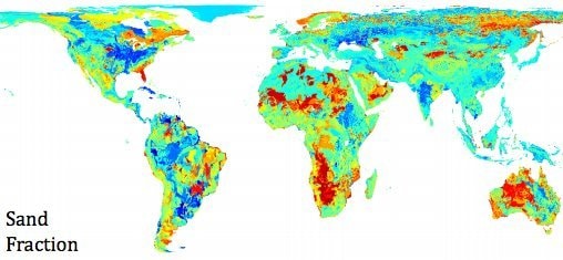 | Harmonized World Soil Database |
| Static Water Fraction | 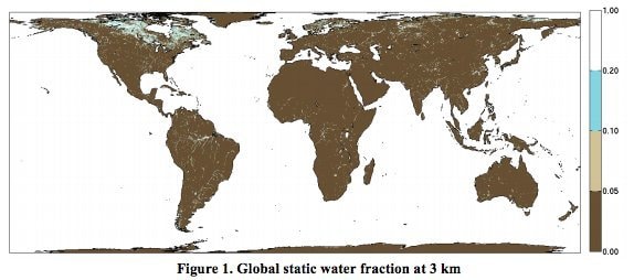 | MODIS Water Mask |
| Urban Area | 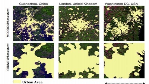 | Gridded Population of the World (GRUMP) |
| Vegetation Water Content | 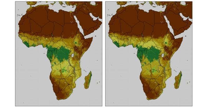 | Normalized Difference Vegetation Index (NDVI) |
| Permanent Ice | 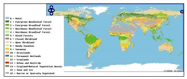 | MODIS Products Table |
| Precipitation | 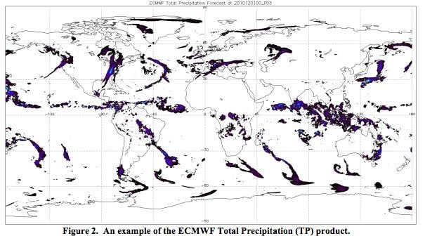 | ECMWF (European Centre for Medium-Range Weather Forecasts) |
Naming Convention — Level 1 Products:
All SMAP Level 1 products represent half orbits. Half-orbit boundaries take place at the northernmost and the southernmost spacecraft location in each orbital path. The most critical identifiers for these products are the orbit number and the designator that specifies the half of the orbit represented by the data.
The following template should be employed to name all SMAP Level 1 products. Note that the orbit number and the half-orbit designator provide the major means of identification.
SMAP_[Product ID]_[Orbit Number]_[A/D]_[First Date/Time Stamp]_[File Version ID].[extension]
Product ID:
The Product ID is based on the Short Name for each SMAP data product—for example: L1A_RADAR. See the table above.
Orbit Number:
A 5-digit orbit number beginning with orbit 00000 on launch. Leading zeros will be used to complete the 5-digit number.
The Half-Orbit Designator:
Division of SMAP orbits into half orbits takes place at the northernmost and southernmost point on the spacecraft path.
“A” indicates ascending; “D” is for descending.
First Date/Time Stamp:
The UTC date/time stamp of the first data element that appears in the product. Format is: YYYYMMDDThhmmss
File Version ID:
A 3-digit number that indicates the version of the data product for the specified half orbit.
Extension:
The products are in HDF5 format; the extension will be .h5.
Example File Names:
SMAP_L1B_TB_00934_A_20141225T074951_003.h5 (ascending)
SMAP_L2_SM_P_01512_D_20150206T210504_005.h5 (descending)