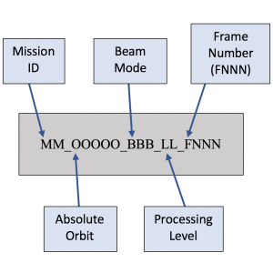
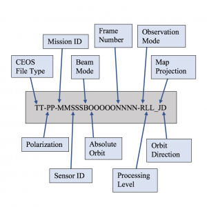
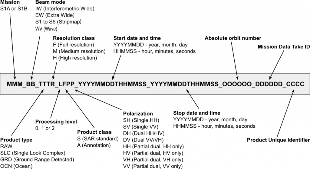
Level 0 Processing Level
Examples:
R1_65186_ST3_L0_F287
E1_25499_STD_L0_F195
E2_84697_STD_L0_F293
J1_29564_STD_L0_F323
Options:
RADARSAT-1 Beam Mode: Extended High (EH3, 4, 6), Extending Low (EL1), Fine (FN1-5), Standard (ST1-7), Wide (WD1-3), ScanSAR — narrow (SNA, SNB), ScanSAR — wide (SWA, SWB).
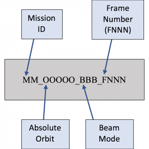
Level 1 Processing Level
Examples:
R1_65186_ST3_F287
E1_25539_STD_F281
E2_82775_STD_F315
J1_28022_STD_F345
Options:
RADARSAT-1 Beam Mode: Extended High (EH3, 4, 6), Extending Low (EL1), Fine (FN1-5), Standard (ST1-7), Wide (WD1-3), ScanSAR — narrow (SNA, SNB), ScanSAR — wide (SWA, SWB).
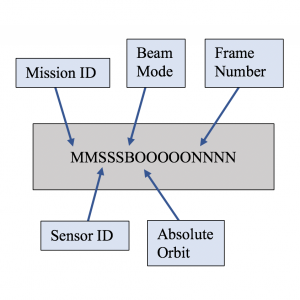
Granule Name
Example:
ALPSRP273981290
Options:
Beam Mode: Wide Beam/ScanSAR (S); Fine single-pol, fine dual-pol, full-pol (P)
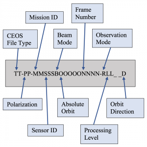
Level 1 Product Name
Example:
IMG-HH-ALPSRP273981290-H1.0__A
Options:
Beam Mode: Wide Beam/ScanSAR (S); Fine single-pol, fine dual-pol, full-pol (P)
Observation Mode: Fine mode (H); Scan SAR mode (W); Direct downlink mode (D); Polarimetry mode (P); Calibration mode (C)
Map Projection: Universal Transverse Mercator/UTM (U); Polar Stereo/PS (P); Mercator (M); Lambert conformal conic/LCC (L); “Not specified” (_ underscore)
Level 1.5 Product Name
Example:
IMG-HH-ALPSRP273981290-H1.5_UA
Options:
Beam Mode: Wide Beam/ScanSAR (S); Fine single-pol, fine dual-pol (P)
Observation Mode: Fine mode (H); ScanSAR mode (W); Direct downlink mode (D); Polarimetry mode (P); Calibration mode (C)
Map Projection: Universal Transverse Mercator/UTM (U); Polar Stereo/PS (P); Mercator (M); Lambert conformal conic/LCC (L); “Not specified” (_ underscore)
Data Name
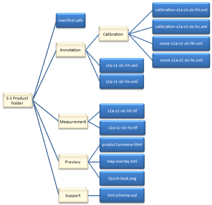
Sentinel-1 products of all processing levels are delivered in the Standard Archive Format for Europe (SAFE) format. The SAFE format packages the data as a file structure which contains other format structures, such as XML, TIF, HTML, KML, PNG, and XSD formats. Measurement data are in GeoTIFF format for Level-1 products.
— Adapted from the European Space Agency
ALOS PALSAR Radiometrically Terrain Corrected (RTC) products are gamma naught, suitable for statistical analysis. For better viewing in GIS, convert to db or amplitude with QGIS or ArcGIS directions.
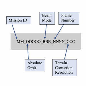
Granule Name
Example:
AP_26939_FBS_F3170_RT1
Options
Beam Mode: Wide Beam/ScanSAR (S); Fine, single-pol, fine dual-pol, full-pol (P)
Terrain Correction Resolution: high resolution (RT1); low resolution (RT2)
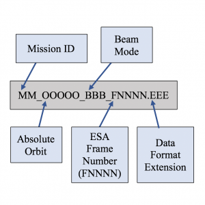
Granule Name
Example:
SS_01492_STD_F2829.tif
Granule Name
Example:
SS_01492_STD_F2829.h5
Product Name
Example:
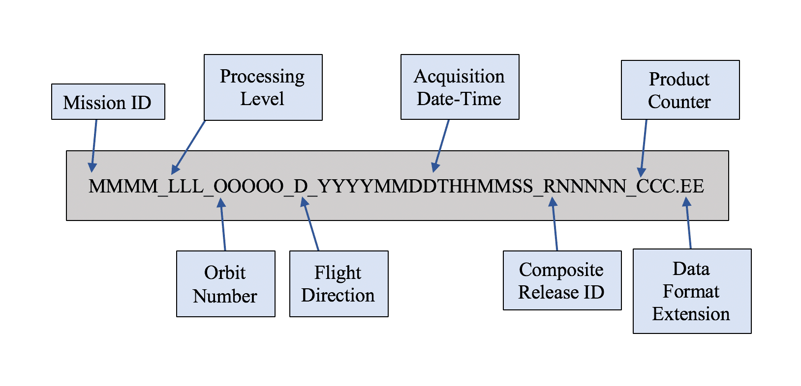
SMAP_L1A_RADAR_00934_A_20141225T074951_R04000_002.h5
Options
Processing Level: L1A_RADAR; L1B_S0_LoRes; L1C_S0_HiRes
Flight Direction: Ascending (A); Descending (D)
Composite Release ID (R is always used)
- Launch indicator: calibration data (0), post-calibration data (1);
- Major ID — incremented by major changes in algorithm or processing approach;
- Minor ID — incremented by changes to data processing, such as algorithm, software, or parameters.
Data Format Extension: HDF5 (.h5); QA products (.qa)
Example:
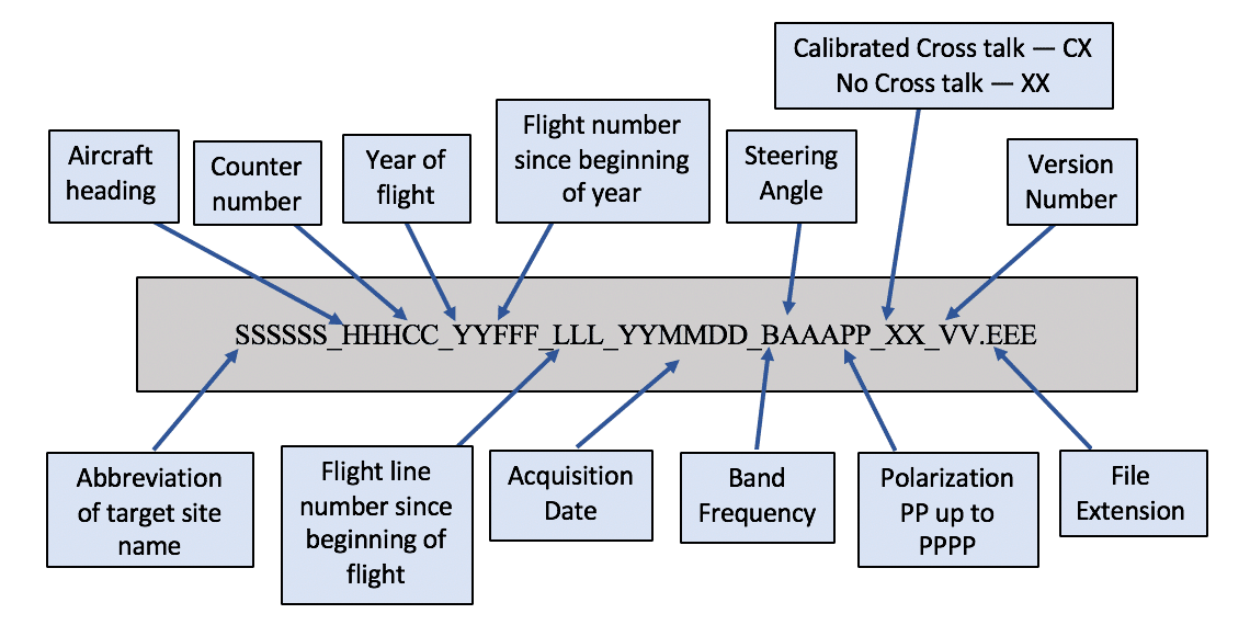
Dthvly_34501_08038_006_080731_L090HH_XX_01.slc
Example:
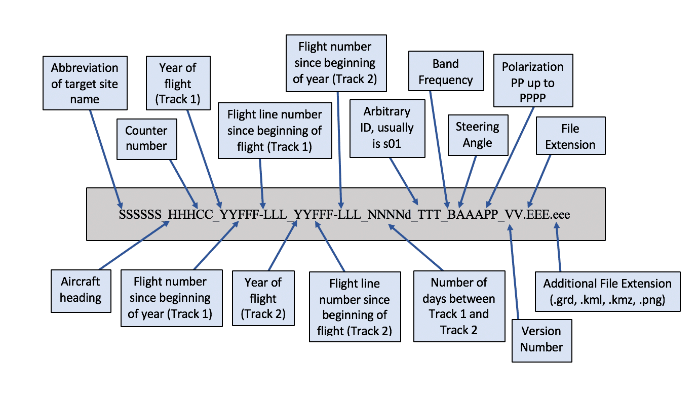
SanAnd_26501_09083-010_10028-000_0174d_s01_L090HH_01.amp1.grd
Product Name
Example:
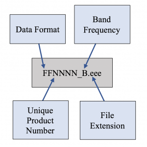
cm4212_l.dat
Options:
Data Format (FF): Compressed Stokes Matrix (cm), Synoptic (sy)
Band Frequency: C-band (c), L-band (l), P-band (p). (Due to FCC restrictions since 1994, P-band data are not included for POLSAR datasets collected at 40 MHz bandwidth over sites in the United States.)
File Extension: .dat, .gif, .airsar, .log
Product Name
Example:
ts1745_p.datgr
Options:
Data Format is TOPSAR (ts).
Band Frequency: C-band (c), L-band (l), P-band (p). (Due to FCC restrictions since 1994, P-band data are not included for POLSAR datasets collected at 40 MHz bandwidth over sites in the United States.)
File Extension: .datgr, .demi2, .log, .airsar, vvi2, .corgr, .incgr, .integer2. (All TOPSAR data, including any polarimetric data collected in a TOPSAR mode, will be projected in the ground range.)