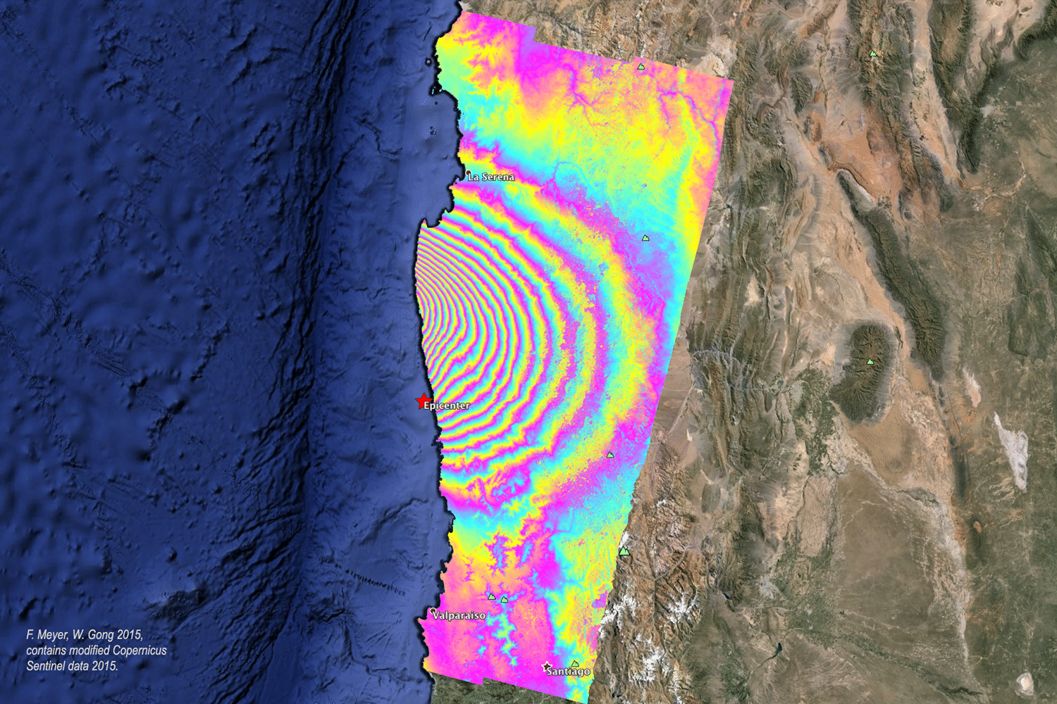
Within days after the 16 September 2015, 8.3 M earthquake in Chile, ASF DAAC scientists used Sentinel-1A acquisitions before and after the quake to create the image at right. The interferogram was unwrapped and rewrapped to a lower fringe rate to improve visual analysis. One fringe (one complete color cycle) corresponds to a relative line-of-sight motion of 8.5 cm. The image is combined with a Landsat image in Google Earth (© 2015 Google). Image credit: F. Meyer, W. Gong 2015; contains modified Copernicus Sentinel data 2015.
by Zhong Lu
A synthetic aperture radar (SAR) system transmits electromagnetic (EM) waves at a wavelength that can range from a few millimeters to tens of centimeters. The radar wave propagates through the atmosphere and interacts with the Earth’s surface. Part of the energy is reflected back to the SAR system and recorded. Using a sophisticated image processing technique, called SAR processing (Curlander and McDonough, 1991), both the intensity and phase of the reflected (or backscattered) signal of each ground resolution element (a few meters to tens of meters) can be calculated in the form of a complex-valued SAR image representing the reflectivity of the ground surface. The amplitude or intensity of the SAR image is determined primarily by terrain slope, surface roughness, and dielectric constants, whereas the phase of the SAR image is determined primarily by the distance between the satellite antenna and the ground targets, slowing of the signal by the atmosphere, and the interaction of EM waves with ground surface. Interferometric SAR (InSAR) imaging, a recently developed remote sensing technique, utilizes the interaction of EM waves, referred to as interference, to measure precise distances. Very simply, InSAR involves the use of two or more SAR images of the same area to extract landscape topography and its deformation patterns.
InSAR is formed by interfering signals from two spatially or temporally separated antennas. The spatial separation of the two antennas is called the baseline. The two antennas may be mounted on a single platform for simultaneous interferometry, the usual implementation for aircraft and spaceborne systems such as Topographic SAR (TOPSAR) and Shuttle Radar Topography Mission (SRTM) systems, where high-resolution, high-precision, digital elevation models (DEM) over large regions can be generated. Alternatively, InSAR can be created by using a single antenna on an airborne or spaceborne platform in nearly identical repeating orbits for repeat-pass interferometry (Massonnet and Feigl, 1998). For the latter case, even though the antennas do not illuminate a given area at the same time, the two sets of signals recorded during the two passes will be highly correlated if the scattering properties of the ground surface remain undisturbed between viewings. This configuration makes InSAR capable of measuring groundsurface deformation with centimeter-to-subcentimeter precision at a spatial resolution of tens of meters over a large region. This is the typical implementation for spaceborne sensors such as the U.S. Seasat (operated June to October, 1978, L-band, wavelength l = 25.0 cm), European Remote-sensing Satellite (ERS-1) (operated 1991-2000, C-band, l = 5.66 cm), Japanese Earth Resources Satellite (JERS-1) (operated 1992-1998, L-band, l = 23.5 cm), Shuttle Imaging Radar-C (SIR-C) (operated April to October 1994, X-, C-, and L-band, l = 3.1 cm, 5.66 cm, and 24.0 cm, respectively), ERS-2 (operating 1995-present, C-band, l = 5.66 cm), Canadian Radar Satellite (RADARSAT-1) (operating 1995-present, C-band, l = 5.66 cm), European Environmental Satellite (Envisat) (operating 2002-present, C-band, l = 5.63 cm), and ALOS (operating 2006-present, L-band, l = 23.6 cm).
An InSAR image (also called an interferogram) is created by co-registering two SAR images and differencing their corresponding phase values on a pixel-by-pixel basis. The phase (or range distance difference) in the original interferogram is due mainly to five effects: (1) differences in the satellite orbits when the two SAR images were acquired, (2) landscape topography, (3) ground deformation, (4) atmospheric propagation delays, and (5) systematic and environmental noises. The knowledge of a satellite’s position and attitude is required to remove the effect caused by the differences in the satellite orbits of the two passes. The topographic effects in the interferogram can be removed by producing a synthetic interferogram, which is created from an accurate DEM and the InSAR imaging geometry, and then subtracting it from the interferogram to be studied.
This is the so-called two-pass InSAR (Massonnet and Feigl, 1998). Alternatively, the topographic contribution can be removed through the use of a different interferogram of the same area. The procedures are then called 3-pass or 4-pass InSAR. These procedures will result in topographyremoved InSAR images, where the component of ground deformation along the satellite’s look direction can potentially be measured with a precision of centimeter or sub-centimeter for C-band sensors, and a few centimeters for L-band sensors. Because of problematic atmospheric propagation delays, repeat observations are critical to confidently interpret small geophysical signals related to movements of the Earth’s surface. Please note, if the two SAR images are acquired simultaneously (single-pass InSAR), or the deformation during the SAR acquisition time is negligible or can be modeled and removed, then the InSAR image can be used to Interferometric Synthetic Aperture Radar: Building Tomorrow’s Tools Today by Zhong Lu derive a DEM. The single-pass InSAR is the fundamental principle for the generation of SRTM DEM.
InSAR Past
The launch of the ERS-1 satellite in 1991 significantly promoted the development of techniques and applications in the field of InSAR. InSAR-related research in the 1990s can be grouped into three categories: deformation mapping, DEM generation, and landscape characterization.
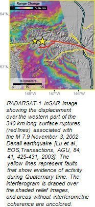
InSAR has been applied successfully to map ground surface deformation during volcanic eruptions and earthquakes. Early studies used SAR images acquired before and after an earthquake or volcanic eruption to image the co-seismic or co-eruptive deformation. Images of InSAR-derived surface deformation can provide essential information about magma dynamics and are extraordinarily useful for understanding slip distribution and rupture dynamics during earthquakes. In the late 1990s, InSAR studies also included the mapping of surface deformation immediately after an earthquake, i.e., post-seismic deformation, while for volcanic study, InSAR was used to map deformation of volcanoes during quiescent periods.
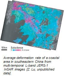
InSAR was applied to map land surface deformation associated with fluid withdrawal. Surface subsidence and uplift that were related to extraction and injection of fluids in groundwater aquifers and petroleum reservoirs could be seen in InSAR images that provided fundamental data on reservoir/aquifer properties and processes, and improved our ability to assess and mitigate undesired consequences. InSAR capability was also demonstrated as an effective way to map the slow movement of landslides, providing a new tool for landslide monitoring.
InSAR was successfully applied to record the movement of glaciers and ice fields, and it significantly advanced the studies of glacier and ice flows, and of ice-sheet mass balance. By regularly imaging ice sheets over the Arctic, Antarctic, and Greenland, InSAR has contributed to building an unprecedented series of snapshots that documents the short-term evolution of the ice sheet, aiding our understanding of their impact on sea level change and global warming.
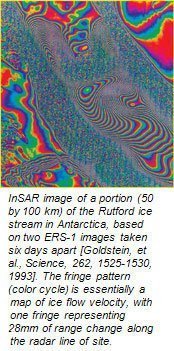
InSAR was applied to map water-level changes over wetlands. InSAR (particularly at longer wavelengths) was found to be an effective tool in the accurate measurement of water-level changes in river valleys and wetlands, which can improve hydrological modeling predictions and enhance the assessment of future flood events over wetlands.
InSAR was applied to construct DEMs over areas where the photographic approach to DEM generation was challenged by inclement weather conditions. For example, repeat-pass InSAR was used to generate ice surface topography that determined the magnitude and direction of the gravitational force that drives ice flow and ice dynamics. In addition, volcano surface topography measurements from before and after an eruption were used to estimate the volume of extruded material. There are many sources of errors in DEM construction: inaccuate determination of the InSAR baseline, atmospheric delay anomalies, and possible surface deformation due to tectonic, volcanic, or other loading sources over the time interval spanned by repeat-pass interferograms, etc. To generate a high-quality DEM from repeat-pass InSAR images, these errors must be corrected.
Finally, InSAR was applied to the study of landscape characterization and changes. InSAR images and their associated products have proved useful to the mapping of flood extents, fire scars, land cover types, changes in soil moisture content, etc.
InSAR Present
In the past few years, deformation mapping with InSAR has advanced from the interpretation of a few InSAR image pairs to the analysis of multi-temporal, time-series InSAR images. The ultimate goal has been to reduce artifacts due to atmospheric delay anomalies, orbit errors, and loss of coherence measurements in order to improve the accuracy of deformation measurements. Stacking and least-squares inversion approaches have been applied to multi-temporal InSAR images to remove atmospheric delay anomalies and improve temporal sampling in order to reveal transient, dynamic deformation patterns.
Persistent Scatterer (PS) InSAR (PSInSAR) represents the most significant advancement in InSAR research. PSInSAR uses unique characteristics of atmospheric delay anomalies and the distinctive backscattering of certain ground targets (called PS) to improve the accuracy of conventional InSAR deformation measurements from 1-2 cm to 2-3 mm (Ferretti, et al., 2001). The SAR backscattering signal of a PS target has broadband spectra in the frequency domain, implying that the radar phase of this kind of scatterer correlates over much longer temporal intervals and over much larger baseline separations than other scatterers. As a result, if the backscattering return of a pixel is dominated by PS(s), this pixel will always be coherent over long time intervals. For PS pixels, the difficulty of decorrelation in the conventional InSAR can, therefore, be overcome. In addition, the atmospheric contribution is rather smooth spatially and is independent over time. At PS pixels, the atmospheric contribution to the received backscattering signal can be identified and removed from the data using a multi-interferogram approach. Therefore, the ultimate goal of PSInSAR processing is to separate the different contributions (surface deformation, atmospheric delay anomaly, DEM error, orbit error, and decorrelation noise) by means of least-squares estimations and iterations, taking into account the spatio-temporal distribution and the correlation between the PS samples. After removing errors due to the atmospheric anomaly, orbit error, and DEM error, deformation histories at PS points can be appreciated at millimeter accuracy. PSInSAR has been successfully applied to monitor landslides, urban subsidence, fault movement, and volcanic deformation.
InSAR Future
The next few years will witness more exciting technical and scientific breakthroughs in many aspects of InSAR. First, longer wavelength SAR images (such as L-band ALOS) will be available that will allow InSAR deformation mapping at global scales where C-band InSAR can be plagued by loss of coherent signal due to vegetation. Second, fully-polarized SAR sensors (ALOS, RADARSAT-2, TerraSAR-X, TanDEM-X, etc.) will allow better characterization of vegetation structure and ground features. The combination of polarimetric and interferometric analysis (called Pol-InSAR) will offer a new capability for landscape mapping and deformation monitoring (Cloude, et al., 2001).
Pol-InSAR will enable optimization procedures that maximize the interferometric coherence and target decomposition approaches to the separation of radar backscattering returns from the canopy top, from the bulk volume of the vegetation, and from the ground surface. The difference in interferometric phase measurements then leads to the difference in height between the physical scatterers that possess these mechanisms. Accordingly, future Pol-InSAR will introduce significant advances in many fields of application: 1) land cover mapping and wetland mapping, particularly over regions where weather conditions hinder optical remote sensing; 2) mapping soil moisture with a horizontal resolution (several meters) that is not attainable otherwise; 3) mapping forest height and biomass with generation of “bare-earth” DEM; 4) traffic monitoring over oceans, and much more.
A third breakthrough is ScanSAR, an advanced SAR imaging technique achieved by periodically switching the antenna look angle into neighboring subswaths in the range direction in order to increase the size of accessible range swath. ScanSAR will be equipped with InSAR capability to enhance spatial coverage of conventional InSAR for large-scale deformation measurement and to improve temporal sampling of InSAR deformation images. Fourth, the atmospheric delays that hamper InSAR accuracy will be lessened by routinely estimating water-vapor content from either the continuous global position system (CGPS) network or other satellite sensors such as Moderate Resolution Imaging Spectroradiometer (MODIS), Advanced Spaceborne Thermal Emission and Reflection Radiometer (ASTER), and European Medium Resolution Imaging Spectrometer (MERIS) to improve InSAR deformation measurements. Fifth, advances in multi-temporal, multi-dimensional datamining techniques (such as PSInSAR) will continue to improve deformation measurement. Finally, automated SAR and InSAR processing systems will be more widely available, which will improve SAR/InSAR processing throughput and lay the foundation for routine monitoring of natural hazards and natural resources.
InSAR is one of the fastest growing fields in the Earth science and remote sensing arenas. With more and more operating SAR sensors available for rapid data acquisitions, armed with state-of-the-art information technologies such as data-mining and grid computation, InSAR will continue to address and unveil many scientific questions related to natural hazard monitoring and natural resource management.
References
Cloude S., K. Papathanassiou, E. Pottier. 2001. Radar Polarimetry and Polarimetric Interferometry. IEICE Transactions on Electronics, E84-C(12), 1814-1822.
Curlander, J. and R. McDonough. 1991. Synthetic Aperture Radar Systems and Signal Processing. New York: John Wiley & Sons.
Ferretti, A., C. Prati, and F. Rocca. 2001. Permanent scatterers in SAR interferometry. IEEE Trans. on Geoscience and Remote Sensing, 39, 8-20.
Massonnet, D., and K. Feigl. 1998. Radar interferometry and its application to changes in the Earth’s surface. Rev. Geophys., 36, 441-500.


