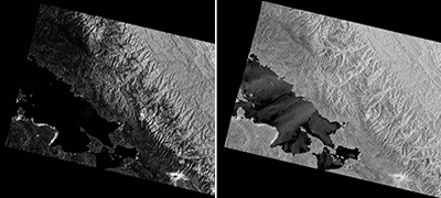
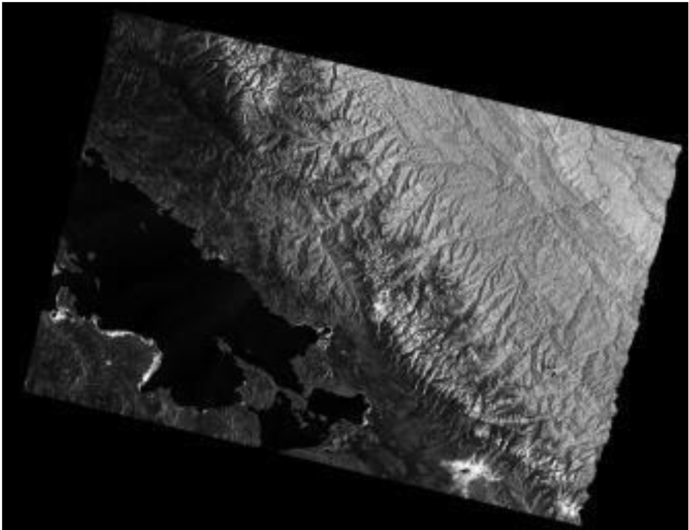
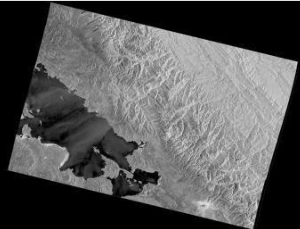
Before and after RTC: In this detail from the test granule below, mountains in Bolivia (left) appear stretched on one side and compressed on the other. RTC (right) moves pixels to unstretch the mountains and adjusts pixel values to subtract the effect of slopes on brightness. Credit left: Copernicus Sentinel data 2015. Credit right: ASF DAAC 2016, contains modified Copernicus Sentinel data 2015, processed by ESA.
Source: ASF Staff
◆ Advanced (Linux): Use GAMMA software and scripts for high-quality results in correcting distortions in synthetic aperture radar (SAR) images. Note: GAMMA requires purchase, a significant cost.
Background
Radiometric correction involves removing the misleading influence of topography on backscatter values. Terrain correction corrects geometric distortions that lead to geolocation errors. The distortions are induced by side-looking (rather than straight-down looking or nadir) imaging, and are compounded by rugged terrain. Terrain correction moves image pixels into the proper spatial relationship with each other. Radiometric terrain correction combines both corrections to produce a more useful product for science applications. This recipe is to support users who are comfortable working in the command line environment and have GAMMA installed on their computers.
ASF provides the perl scripts “rtc_sentinel_recipe.pl” and “utm2dem_i2.pl” to radiometrically terrain correct Sentinel-1A GRD data using GAMMA software. This script uses a DEM file and a Sentinel-1A granule as inputs and creates terrain-corrected GeoTIFFs of each polarization, an incidence angle map, a layover/shadow map, and a clipped DEM file that matches the area of the SAR image.
Prerequisites
Materials List:
- Sentinel-1A GRD product (download granule of your choice from Vertex or use Sample Granule)
- Digital Elevation Model (DEM) (available from many sources, including USGS Earth Explorer and OpenTopography; choose projection in meters)
- GAMMA software package (MSP + ISP + DIF&GEO + LAT). Note: GAMMA requires purchase, a significant expense.
- GDAL warp (part of GDAL Utilities)
- rtc_sentinel_recipe.pl (included in the Data Recipe zip button at the top of this recipe)
- utm2dem_i2.pl (included in the Data Recipe zip button at the top of this recipe)
Steps
- Download and install in your local environment the GAMMA software package.
- Download and install the most recent version of GDAL utilities; this will include gdalwarp. To do this for the Linux operating system Ubuntu, for example, use apt-get: (sudo apt-get install gdal-bin).
- Put the rtc_sentinel_recipe.pl script and the utm2dem_i2.pl into a directory that is in your path. Modify your path if necessary using “export PATH=$PATH:~[desired directory]”.
- To turn these scripts into executable files, change into the directory the scripts are saved in and enter “chmod a+x *”.
- Create a directory to house the Sentinel-1A GRD products (the .zip file).
- Download a Sentinel-1A GRD granule from ASF Vertex and move it to your GAMMA processing directory. (Sample granule available).
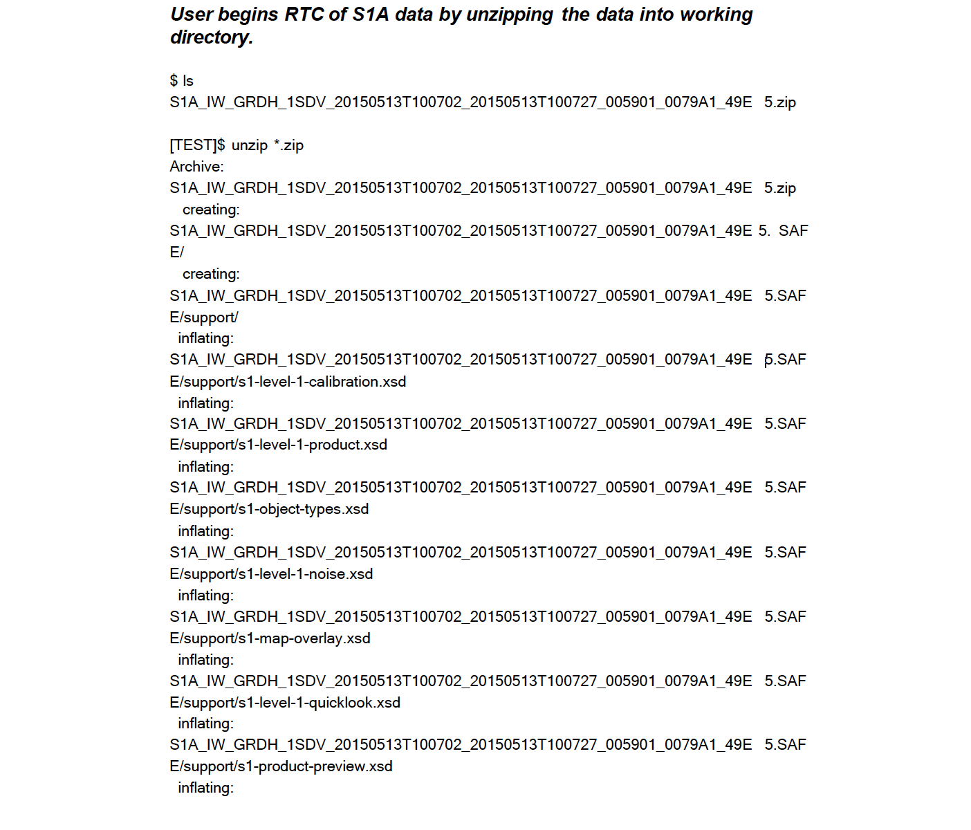
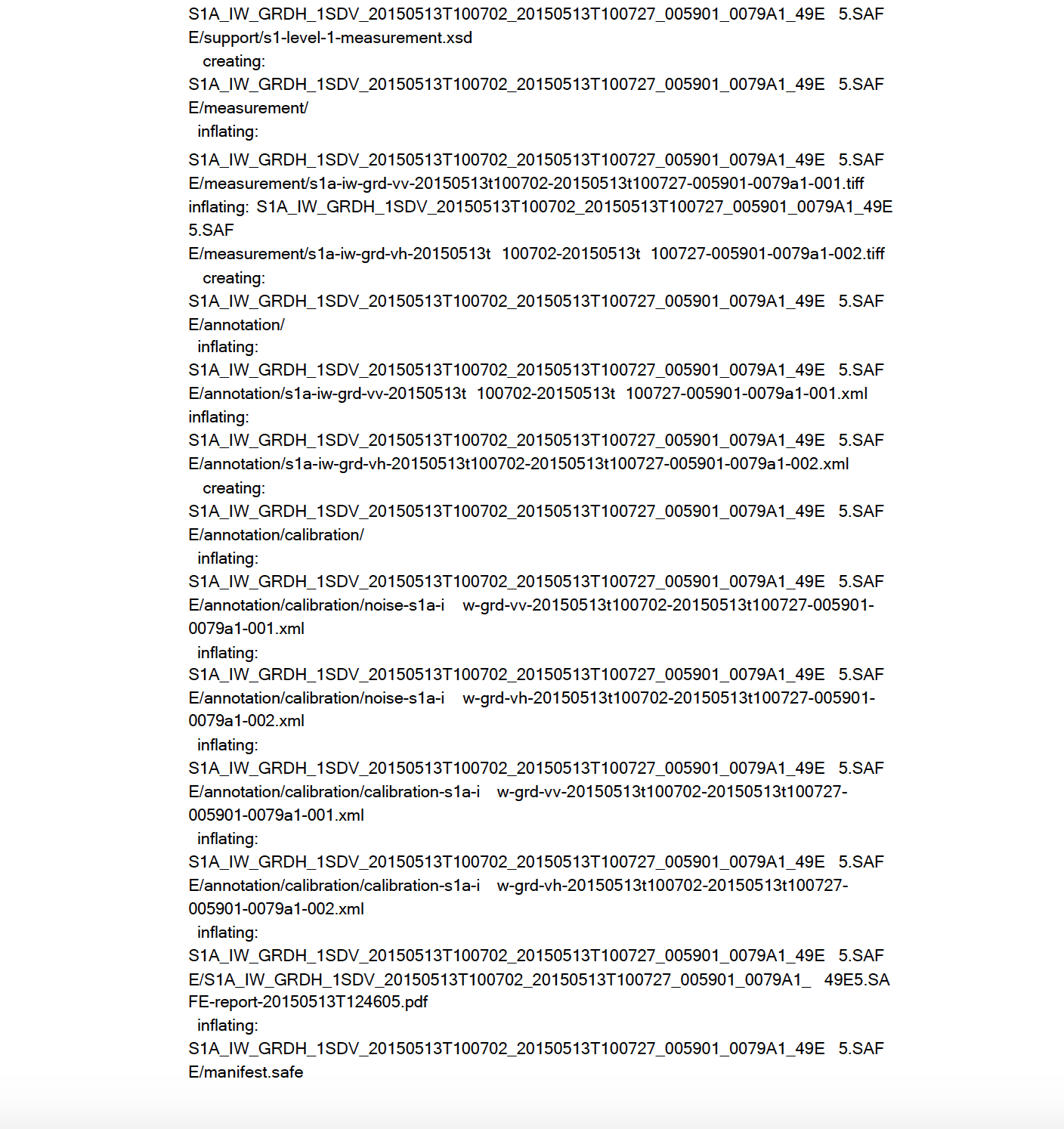
- Unzip the Sentinel-1A GRD file in your processing directory.
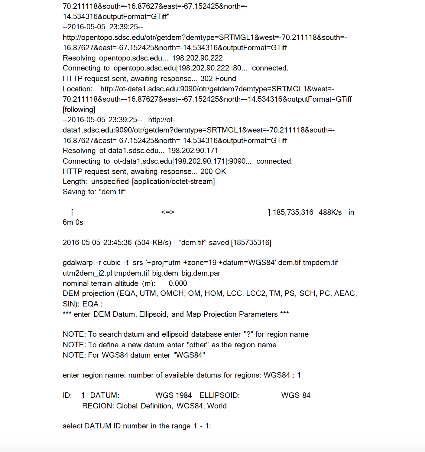
- Download a DEM: The script will automatically download and apply an SRTMGL1 DEM file from OpenTopo, or you may use a DEM of your choice.
Note: If you want to use your own DEM, download an external DEM and corresponding par file in GAMMA format, and place in GAMMA processing directory. The downloaded DEM must be in GAMMA format (DEM and par file).
- The following options are available when running the script:
- output Output RTC filename
- -e dem (option) sepcify a DEM file to use (with par file), e.g., big.dem to specify big.dem and big.dem.par
- -r res (option) specify the output resolution (default 10 meters)
- Run the script:
- The following options are available when running the script:
perl rtc_sentinel_recipe.pl [options] <output filename>
Output
Once the script has finished running, the main output can be found in the PRODUCT directory. The PRODUCT directory will contain the 4 or 5 output product files — one for each polarization (e.g., VV or VV and VH), one for the incidence angle map (inc_map), one for the layover/shadow map (ls_map), and one for the clipped DEM file (dem).
Here is a sample PRODUCT directory listing:
ls -1 PRODUCT/
s1a-iw-rtc-20150513T100702-dem.tif
s1a-iw-rtc-20150513T100702-inc_map.tif
s1a-iw-rtc-20150513T100702-ls_map.tif
s1a-iw-rtc-20150513T100702-vh.tif
s1a-iw-rtc-20150513T100702-vv.tif
Many intermediate files are left in the current working directory as well as several sub-directories being created after the run has completed. These files can be deleted once processing of the RTC products has completed. Below is a list of the intermediate files that do not need to be archived further.
ls -1 20150513T100702.log
20150513T100702.vh.GRD
20150513T100702.vh.GRD.par
20150513T100702.vh.mgrd
20150513T100702.vh.mgrd.bmp
20150513T100702.vh.mgrd.ellipse_cal
20150513T100702.vh.mgrd.par
20150513T100702.vv.GRD
20150513T100702.vv.GRD.par
20150513T100702.vv.mgrd
20150513T100702.vv.mgrd.bmp
20150513T100702.vv.mgrd.ellipse_cal
20150513T100702.vv.mgrd.par
asf_utm2dem.log
big.dem big.dem.par
dem_par.in dem.tif geo_vh
geo_vv
PRODUCT
S1A_IW_GRDH_1SDV_20150513T100702_20150513T100727_005901_0079A1_49
E5.SAFE
S1A_IW_GRDH_1SDV_20150513T100702_20150513T100727_005901_0079A1_49
E5.zip
tmpdem.tif
utm_tmp.aux.xml
utm_tmp.hdr
Before and After Images
How the Perl Scripts Work
Given the following:
| pol | polarization being worked on |
| output | output name |
| res | desired output resolution |
| look_fact | calculated look factor = int($res/10+0.5) |
| dem | input DEM file |
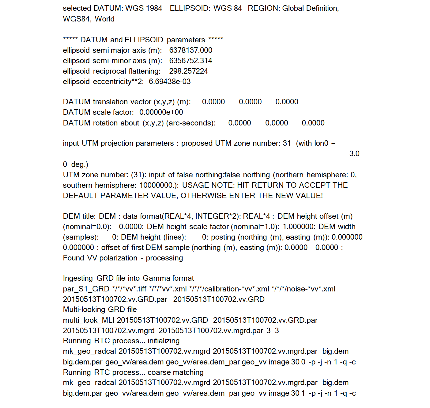
- Ingests the data into GAMMA format to begin radiometric terrain correction of the main polarization data.
par_S1_GRD */*/*$pol*.tiff */*/*$pol*.xml */*/*/calibration-*$pol*.xml
*/*/*/noise-*$pol*.xml $output.$pol.GRD.par $output.$pol.GRD
- (Optional if users use -r res) Multi-looks the data to the desired resolution.
multi_look_MLI $output.$pol.GRD $output.$pol.GRD.par
$output.$pol.mgrd $output.$pol.mgrd.par $look_fact $look_fact
Note: Multi-looking will not be performed if $look_fact < 2.
- Converts the data from ground range to slant range.
GRD_to_SR $output.$pol.mgrd.par $output.$pol.mli.par –
$output.$pol.mgrd $output.$pol.mli 1 1 2 $res $res
- Generates initial lookup table, simulated SAR image, and DEM segment parameters; erases existing DEM segment parameters.
mk_geo_radcal.pl $output.$pol.mli $output.$pol.mli.par $dem
$dem.par geo_$pol/area.dem geo_$pol/area.dem_par geo_$pol image $res 0 -p -j -n 1 -q -c
Here, the options used are as follows:
| -p | use the pixel area program to create simulated SAR image |
| -j | don't use layover-shadow map in pixel area calculation |
| | use a first-order mapping function |
| -q | quiet mode — don't display intermediate results |
| -c | create calibrated output files |
- Measures initial offset between simulated SAR image and actual SAR image.
mk_geo_radcal.pl $output.$pol.mli $output.$pol.mli.par $dem
$dem.par geo_$pol/area.dem geo_$pol/area.dem_par geo_$pol image $res 1 -p -j -n 1 -q -c
- Performs refinement of lookup table by offset measurement with respect to the simulated SAR image.
mk_geo_radcal.pl $output.$pol.mli $output.$pol.mli.par $dem
$dem.par geo_$pol/area.dem geo_$pol/area.dem_par geo_$pol image $res 2 -p -j -n 1 -q -c
- Updates lookup table and produce terrain-geocoded SAR image and DEM in SAR range-Doppler coordinates (RDC).
mk_geo_radcal.pl $output.$pol.mli $output.$pol.mli.par $dem
$dem.par geo_$pol/area.dem geo_$pol/area.dem_par geo_$pol image $res 3 -p -j -n 1 -q -c
Note: Once the first polarization is completed, the second polarization proceeds as follows (assuming it exists):
- Ingests the data into GAMMA format to perform terrain correction on the second polarization.
par_S1_GRD */*/*$pol*.tiff */*/*$pol*.xml */*/*/calibration-*$pol*.xml
*/*/*/noise-*$pol*.xml $output.$pol.GRD.par $output.$pol.GRD
- Multi-looks the data to the desired resolution (optional step)
multi_look_MLI $output.$pol.GRD $output.$pol.GRD.par
$output.$pol.mgrd $output.$pol.mgrd.par $look_fact $look_fact
Note that multi-looking will not be performed if $look_fact < 2.
- Converts the data from ground range to slant range.
GRD_to_SR $output.$pol.mgrd.par $output.$pol.mli.par –
$output.$pol.mgrd $output.$pol.mli 1 1 2 $res $res
- Performs refinement of lookup table by offset measurement with respect to the simulated SAR image.
mk_geo_radcal.pl $output.$pol2.mli $output.$pol2.mli.par $dem
$dem.par geo_$pol1/area.dem geo_$pol1/area.dem_par geo_$pol2image $res 3 -p -j -n 1 -q -c
Note: $pol2 is the cross-polarization and $pol1 is the main polarization.
Example Run