






The Alaska Satellite Facility (ASF) operates four satellite tracking and communications antennas that are part of the NASA Near Space Network (NSN)
ASF is a key ground support facility in NASA’s satellite-based Earth Observation Network. ASF also operates an antenna that is a part of the Viasat Real Time Earth satellite-to-ground global communications network.
The NASA ground station serves as a critical hub for acquiring data from Earth-observing satellites equipped with a variety of remote-sensing instruments, including synthetic aperture radar (SAR). The location of the facility at UAF in Fairbanks was strategically chosen by NASA for its reliable power and communications, and for its high-latitude location, offering frequent contact with polar-orbiting satellites passing overhead.
The ground station

ASF provides 24-hour-a-day infrastructure support and operational expertise, which enables the reliable acquisition of satellite remote-sensing data. This, in turn, allows researchers, government agencies, and other customers access to these data for a wide range of applications, and contributes to a better understanding of Earth’s natural processes.
Explore the 360º view below using your mouse, arrow keys, or a touch screen.

One of the ASF NASA antennas surrounded by the golden colors of birch tree fall foliage.
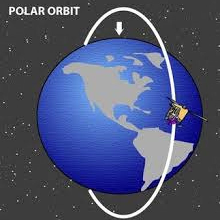
Illustration of the trajectory of a polar orbiting satellite.
Satellite acquisition schedule - The "Airline Display"
Recorded February 8th and 9th, 2025
This video shows the monitor (the “Airline Display”) in the ground station control room displaying the schedule for upcoming satellite passes over Interior Alaska for which the NSN will provide communication support. Information includes: the antenna providing support (AS1-AS4), the satellite, the satellite’s orbit number, the transmission band (S, X, Ka), and the start, stop, and duration of the transmission.
NSN antennas AS1-AS3 are located at the UAF campus, while AS4 is located at a site on the Richardson Highway, 12 miles from Fairbanks.
Satellites tracked
| Term or Acronym | Description |
|---|---|
| AQA | Aqua is a NASA Earth Science satellite mission collecting information about the Earth’s water cycle, including evaporation from the oceans, water vapor in the atmosphere, clouds, precipitation, soil moisture, sea ice, land ice, and snow cover on the land and ice. Aqua was launched on May 4, 2002. |
| AUR | Aura is designed to answer questions about changes in Earth’s atmosphere. Aura’s four instruments study atmospheric chemistry and dynamics, enabling us to investigate questions about ozone trends, air quality changes, and their links to climate change. The Aura spacecraft was launched on July 15, 2004. |
| IC2 | The Ice, Cloud, and Land Elevation Satellite-2, or ICESat-2, measures the height of a changing Earth, one laser pulse at a time, and 10,000 laser pulses a second. Launched September 15, 2018, ICESat-2 carries this photon-counting laser altimeter to allow scientists to measure the elevation of ice sheets, glaciers, sea ice, and more. |
| PAC | The Plankton, Aerosol, Cloud, ocean Ecosystem (PACE) spacecraft is helping us better understand how the ocean and atmosphere exchange carbon dioxide, as well as revealing how aerosols might fuel phytoplankton growth in the surface ocean. PACE launched on February 8, 2024. |
| SMP | The Soil Moisture Active Passive (SMAP) mission is an orbiting observatory that measures the amount of water in the surface soil everywhere on Earth. It was launched in January 2015 and started operation in April 2015. |
| Orbit | Each satellite completes about 14 orbits per day. Aqua’s 121,000+ orbits, for example, equates to more than 23 years of operation, tracking, and data acquisition. |
| AOS | Acquisition of Signal (UTC) |
| LOS | Loss of Signal (UTC) |
The Antenna display
The AS2 and other ASF antennas track near space satellites during “passes,” when a satellite is above the antenna’s horizon. Once a connection is established, data collected by the satellite may be sent down to the antenna and Ground Station. Each satellite is in a set orbit, and the antenna is able to follow along a predetermined, known path determined by the satellite mission.
Explore the 360º view below using your mouse, arrow keys, or a touch screen.
How does the antenna move?
Station mask and simulation
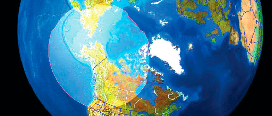
The “station mask” is the area on the Earth’s surface within which a satellite is visible to one of the NSN antennas operated by ASF.
The 4-minute-long video below simulates the movement of the AS2 antenna as it provides communication support for a satellite passing through the ASF station mask. The antenna receives a command to move and point exactly where on the horizon the satellite is predicted to appear. Once contact is made, the communication session begins, and the antenna will automatically track the satellite as it moves overhead. The communication session is terminated before the satellite disappears on the opposite horizon.
In the video, narration begins at about time 2:50.
Terms used when orienting the antenna
Azimuth measured from 0° (North) to 360° in a clockwise direction. An azimuth of 90° would be East, and an azimuth of 180° would be South.
Elevation is the vertical angle of the antenna, measured from the horizon. An elevation of 0° is the horizon, and an elevation of 90° is directly overhead (zenith).
Train is a third axis that allows the antenna to shift its “directly overhead” or “keyhole” away from the expected path of the satellite. The antenna will need to rotate much, much faster when tracking a satellite overhead compared to one on the horizon. Without the train axis, these speeds could be too fast for the antenna to maintain contact with the satellite.
Corner reflectors and control points
Highly visible to radar, a corner reflector bounces a satellite’s radar signal directly back to the spacecraft sensor, creating a bright, identifiable dot in a SAR image. An array of ASF corner reflectors is deployed in Delta Junction, Alaska, where they are used to calibrate satellite radar images. Another full-sized corner reflector can be seen to the west of the museum along the serpentine road running past the Geophysical Institute.
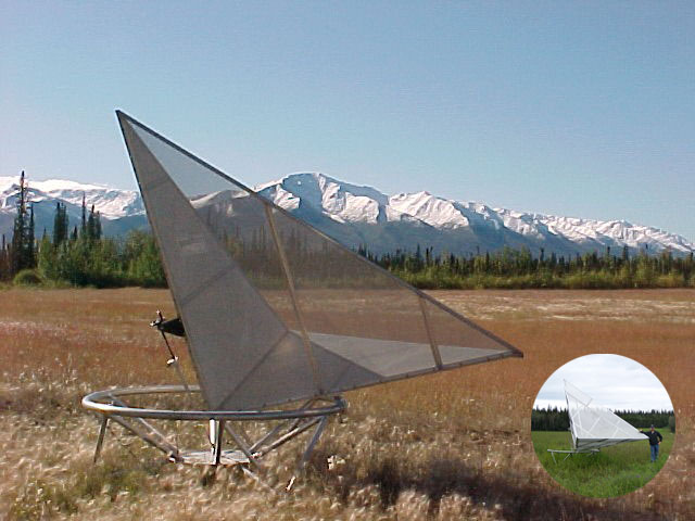
A corner reflector measuring 3 meters wide sits in a field in Fairbanks. The insert illustrates the scale of the installation compared to a person.
The animation below is an illustration of how a wave reflects back to the transmitter through a corner reflector.
A surveyor’s corner cube works in the same way that the radar corner reflector does, only with visible light. Outgoing rays of light are parallel to the incoming rays, which is why your eye will always appear in the center of the device.