Global Ice Sheet Mapping Orbiter (GISMO)
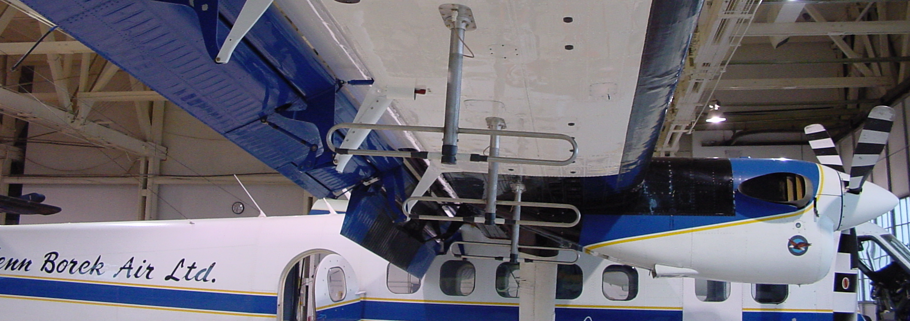
The Global Ice-Sheet Mapping Observatory (GISMO) radar system was a part of the NASA Instrument Incubator Project (IIP). The IIP program was designed to provide a testing opportunity for emerging technology in order to create smaller and more efficient flight instruments. GISMO had a specific focus in measuring the surface topography of ice sheets, ice-sheet thickness, and in uncovering physical properties of the glacier bed using synthetic aperture radar (SAR).
The photo shows the GISMO instrument antennas mounted to the wing of a P-3 Orion aircraft. The instrument was flown as a concept for an eventual spaceborne radar system.

The Global Ice-Sheet Mapping Observatory (GISMO) spaceborne radar system was a part of the NASA Instrument Incubator Project (IIP). The IIP program was designed to provide a testing opportunity for emerging technology in order to create smaller and more efficient flight instruments. GISMO had a specific focus in measuring the surface topography of ice sheets, ice-sheet thickness, and in uncovering physical properties of the glacier bed using synthetic aperture radar (SAR).
The GIMSO project lasted for three years and had documented flight lines over the Greenland Ice Sheet in 2006, 2007, and 2008. It utilized VHF and P-band interferometric radars and tested different methods of clutter rejection in order to find the method most suitable for the project’s focus.
GISMO achieved mapping the physical properties of a glacier bed through up to 5 km of ice. It also created an effective clutter rejection technique for measuring the ice sheet’s surface and base. GISMO has applications in predicting the effects of climate change on ice sheets and in exploring planets with icy areas.
Expand the sections below to view content. Access the full content on a single page by clicking the button.
Public Access Documents. Click on the document name to download it.
Radar
Radar Design Trade-off
Antenna Pattern
Antenna Pattern Excel Sheet
InSAR Concept
InSAR Parameters Trade Study
Radar Parameters
Radar Electronics Design
P-3 Antennas
Photo
Geophysical requirements
Dimensions of Subglacial Water Bodies
Thickness Accuracy
GISMO Antenna Design Report for April 07 Experiment
Antenna Report from KU
GISMO Processing Diagram
GISMO Processing Diagram
2005 Team Meeting and Documents
Click on the document name to download it. Note: Some team documents are not available.
2005 Documents
GISMO Response to NRC Decadal Survey RFI
GISMO Meeting Agenda Sept 2005
GISMO Science Requirements
GISMO QUAD Chart
GISMO Team Meeting, Sept. 2005, Algonquin State Park
Final Agenda
Science Requirements (Jezek)
KU Radar (Gogineni)
GISMO Concept (Rodriguez)
Simulations (Wu)
Subglacial Topography (Tulaczyk)
GISMO DEM (Jezek)
Ionospheric Effects (Freeman)
Project Links (Jezek)
ESTO Reporting Requirements (Jezek)
Aircraft Options Summary
2005 Reports
2006 Team Meeting and Documents
January 2006 Mid-year Review
February 2006 Airborne Experiment Meeting WFF
Vu-graph Package
Meeting Summary
May 2006 Team Meeting, Vexcel Corp
Agenda, Summary, Plans
Radar Status
Airborne Simulations
May 06 Field Study Summary
Surface-based SAR Summary
Cards Data Format
Scattering Models
Planning Meeting for April 07 — WFF October 06
Overview (Jezek)
Review of May 06 Radar (Gogineni)
Review of May 06 Navigation (Sonntag)
Lessons Learned
Radar for 07 (Gogineni)
Flight Organization (Valiant)
2006 Reports
Jan 2006
March 2006
May 2006
Year 1 Annual Report (.doc)
Year 1 Annual Report (.pdf)
Year 1 Review (.ppt)
August 2006
December 2006
May 2006 Field Program
Experiment Operations Plan
Related Flight Locations
Preflight Planning and Analysis
Motion Data
Motion Data Description
Precise Trajectory
Precise Trajectory Readme
Ice-thickness plots
Ice Thickness 1
Ice Thickness 2
Ice Thickness 3
Ice thickness 4
2007 Team Meetings and Documents
Click on the document name to download it. Note: Some team documents are not available.
January 2007 Mid-year Review
Mid-year Review Vu-graphs
Mid-year Review Vu-graphs Updated Post Review
GISMO Team Meeting JPL, January 31
PARCA Presentation (Rodriguez)
Progress to Date
Status and Summary of Mid-year Review, Budget Issues (Jezek)
Planning for April 07 Experiment
Science and Engineering Objectives for April 2007 (Jezek)
Radar and Antenna Status (Gogineni)
Vexcel Data Processing Status, Interface and Readiness (Refraction, Motion Compensation, Calibration) (Wu)
JPL Data Processing Status, Interface and Readiness (Refraction, Motion Compensation, Calibration) (Rodriguez)
Navigation (Sonntag)
Arctic 07 Planning Status and Key Milestones (Krabill)
Proposed Flight Lines 1, 2, 3 (Fahnestock and Sonntag) and Discussion
April 07 Experiment Plan and Discussion (Jezek) (see May 06 vu-graphs for sample experiment plan form)
Algorithms, February 1
Tomography Algorithm Status (Wu) (covered above)
InSAR Algorithm Status (Rodriguez)
Update on Multiaperture Beam Processing (Gogineni) (covered above)
Plans for Reducing May 2006 Data to Topography (Wu, Rodriguez, Forster)
Plans for Investigating Ionospheric Effects and Corrections (Freeman)
Data Management Issues, Schedule for Delivery of April 07 Data, Action Items (Jezek)
Vexcel Algorithm Meeting, June 2007
Agenda
Processor Review
Summary and Action Items
Updated InSAR Equation
June 2007 Mid-year Review
2007 Annual Review
Freeman Backup Vu-graphs to Annual Review
August 2007 Radar Readiness Review (KU)
Readiness Review (Gogineni)
Digital Systems (Ledford)
Calibration (Rodriguez)
Processor Status (Wu)
Experiment Plan (Jezek)
Thin Layer Model (Niamsuwan)
2007 Biannual Reports
April 2007 Field Program
Calibration and Geometry Check List
Experiment Plan
Experiment Summary
Radar data available from KU (about 5 Gb)
Motion Data
September 2007 Field Program
Pre Mission
Calibration and Geometry Check List
Experiment Plan
Schedule
Range Window Analysis
Post Mission
Trip Report
Radar Calibration Report
Post Mission Data Review
Ice Sheet Roughness Report
Quick-look Motion Files
070907
070908
070910
070911
070912
070914
070915
070918
KU GPS Files
070907
070908
070910
070911
070912
070914
070915
070918
Sample Data
Sept 11 150 Gismo 22000ft Ice Stream
Sept 8 450 GISMO 22000ft Ice Stream
Sept 12 150 GISMO 1500 FT Ice Stream: File 1, File 2
2008
Sonde to Summit Topography
File Downloads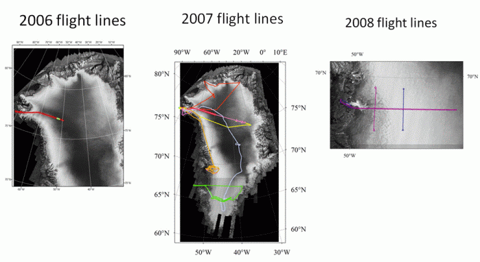
Data description
Bed data format
Bed data
Surface format
Surface data
July 08 Dataset
May 23, 2006, 150 MHz Data Products
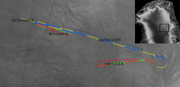
Each flight line was segmented into approximately 25 km long sections with 20% overlap on each end. Each segment contains the following data in a zip file:
1. Thickness data 32 bit float binary, 10 m pixel resolution ‘seg#_thickness’
2. Thickness data GeoTIFF ‘seg#_thickness_geo.tif’
3. Thickness data graphic ‘seg#_thickness.gif’
4. Image data 32 bit float binary, 10 m pixel resolution ‘seg#_image’
5. Image data GeoTIFF ‘seg#_image_geo.tif’
6. Image data graphic ‘seg#_image.gif’
7. Header file with columns, rows, projection information, and corner map coordinates ‘seg#.hdr’
8. ASCII file with latitude, longitude, and aircraft altitude of corresponding segment ‘seg#_0_0.pos’ where the last two numbers represent waveform and channel. There are 4 waveforms and as many as 8 channels.
‘seg#’ refers to the segment number ie: 0_3, 3_7, 7_11 etc.
Products
GISMO – May 23, 2006, Outbound Flight Line
products for segment 0_3 | 0_3_thickness.gif
products for segment 3_7 | 3_7_thickness.gif
products for segment 7_11 | 7_11_thickness.gif
products for segment 11_15 | 11_15_thickness.gif
products for segment 15_19 | 15_19_thickness.gif
products for segment 19_23 | 19_23_thickness.gif
products for segment 23_27 | 23_27_thickness.gif
products for segment 27_31 | 27_31_thickness.gif
products for segment 31_34 | 31_34_thickness.gif
products for segment 34_38 | 34_38_thickness.gif
products for segment 38_42 | 38_42_thickness.gif
GISMO – May 23, 2006, Inbound Flight Line
products for segment 42_46 | 42_46_thickness.gif
products for segment 46_50 | 46_50_thickness.gif
products for segment 50_54 | 50_54_thickness.gif
products for segment 54_58 | 54_58_thickness.gif
products for segment 58_62 | 58_62_thickness.gif
products for segment 62_66 | 62_66_thickness.gif
products for segment 66_70 | 66_70_thickness.gif
products for segment 70_74 | 70_74_thickness.gif
products for segment 74_78 | 74_78_thickness.gif
products for segment 78_82 | 78_82_thickness.gif
products for segment 82_86 | 82_86_thickness.gif
products for segment 86_89 | 86_89_thickness.gif
Sept 10, 2007, 450 MHz Data Products
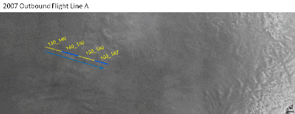
Each flight line was segmented into approximately 25 km long sections with 20% overlap on each end. Since there were only 4 channels for these data, good left-right separation was not possible, thus there is no image or thickness data available for 2007. The following is what is included in the product zip files:
1. ASCII file with latitude, longitude, and aircraft altitude of corresponding segment ‘seg#_0_0.pos’ where the last two numbers represent waveform and channel. There are 4 waveforms and as many as 8 channels.
2. 450 MHz (Sept 10) intensity data 32 bit float binary, 5X25 m (pixel x line) resolution which includes both the surface and base part. Slant range imagery can be used to get the nadir thickness information. ‘seg#_inten’
3. Azimuth compressed header file with column, row, resolution, wavelength, and # looks ‘seg#_0_0.azcom.par’
4. Azimuth compressed nadir file with latitude, longitude of first pixel of each azimuth line in the slant range image, aircraft altitude, and roll angle in degrees (last column) ‘seg#_0_0.azcom.nadir’
5. 450 MHz (Sept 10) Surface/Base profile gives an estimate (may not be exact in some areas) of the surface and the base profile. ‘seg#_surface_base.profile’ *note not all segments have this file*
Ice_elevation = (base_pixel – surface_pixel)*5.0/1.8 (m)
‘seg#’ refers to the segment number ie: 0_3, 3_7, 7_11, 100_110 etc.
Products
products for segment 130_140
products for segment 140_150
products for segment 150_160
products for segment 160_167
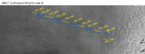
products for segment 194_200
products for segment 200_210
products for segment 210_220
products for segment 220_230
products for segment 230_240
products for segment 240_250
products for segment 250_260
products for segment 260_269
products for segment 271_280
products for segment 280_288
products for segment 290_296
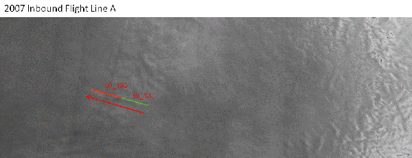
products for segment 169_180
products for segment 180_192
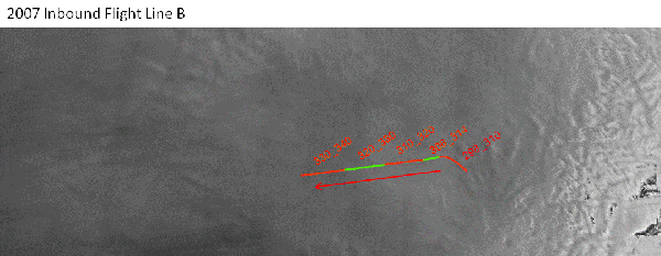
products for segment 298_310
products for segment 306_314
products for segment 310_320
products for segment 320_330
products for segment 330_340
Sept 12, 2007, 150 MHz Data Products
Each flight line was segmented into approximately 25 km long sections with 20% overlap on each end. Since there were only 4 channels for these data, good left-right separation was not possible, thus there is no image or thickness data available. The following is what is included in the product zip files:
1. ASCII file with latitude, longitude, and aircraft altitude of corresponding segment ‘seg#_0_0.pos’
2. 150 MHz (Sept 12) Intensity data 32 bit float binary, 5X25 m (pixel x line) resolution which includes both the surface and base part. Slant range imagery can be used to get the nadir thickness information. ‘seg#_inten’
3. Azimuth compressed header file with column, row, resolution, wavelength, and # looks ‘seg#_0_0.azcom.par’
4. Azimuth compressed nadir file with latitude, longitude of first pixel of each azimuth line in the slant range image, aircraft altitude, and roll angle in degrees (last column) ‘seg#_0_0.azcom.nadir’
5. 150 MHz (Sept 10) Surface/Base profile gives an estimate (may not be exact in some areas) of the surface and the base profile. ‘seg#_surface_base.profile’
Ice_elevation = (base_pixel – surface_pixel)*5.0/1.8 (m)
6. Image, thickness, and header data for two segments 450_460 and 480_490 ‘seg#_image, seg#_thickness, and seg#.hdr’
7. Image and thickness GeoTIFF’s for segments 450_460 and 480_490 ‘seg#_image_geo.tif’ and ‘seg#_thickness_geo.tif’
8. Thickness data graphic for segments 450_460 and 480_490 ‘seg#.thickness.tiff’
‘seg#’ refers to the segment number ie: 0_3, 3_7, 7_11, 100_110 etc.
Products
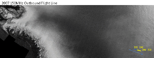
products for segment 231_240
products for segment 240_250

products for segment 255_262
products for segment 270_280
products for segment 280_290
products for segment 290_300
products for segment 300_310
products for segment 310_320
products for segment 320_330
products for segment 330_340
products for segment 340_350
products for segment 350_360
products for segment 360_370
products for segment 370_380
products for segment 380_390
products for segment 390_400
products for segment 400_410
products for segment 410_420
products for segment 420_430
products for segment 430_440
products for segment 440_450
products for segment 450_460 | 450_460.thickness.tiff
products for segment 460_470
products for segment 470_480
products for segment 480_490 | 480_490.thickness.tiff
products for segment 490_500
2008 Low Aircraft Elevation Data Products
Each flight line was segmented into approximately 25 km long sections with 20% overlap on each end. Each segment contains the following data in a zip file:
1. Thickness data 32 bit float binary, 20 m pixel resolution ‘seg#_thickness’
2. Thickness data GeoTIFF, 20 m, ‘seg#_thickness_geo.tif’
3. Thickness data graphic ‘seg#.thickness.tiff’
4. Image data 32 bit float binary, 20 m pixel resolution ‘seg#_image’
5. Image data GeoTIFF, 20 m, ‘seg#_image_geo.tif’
6. Header file with columns, rows, projection information, and corner map coordinates ‘seg#.hdr’
7. ASCII file with latitude, longitude, and aircraft altitude of corresponding segment ‘seg#_0_0.pos’ where the last two numbers represent waveform and channel. There are 4 waveforms and as many as 8 channels.
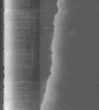
8. Intensity graphic ‘seg#_inten.tif’ where the along track is in the vertical direction and the cross track (slant range) is in the horizontal direction from left to right. The brightest part on the left is the ice surface. There are discontinuities between the surface and the base resulting from different azimuth looks. Only two looks are used to create the surface portion (left) and 20 looks are used to create the base portion (right). The white line (right) represents the base and is an estimate of the nadir profile.
‘seg#’ refers to the segment number ie: 0_3, 3_7, 7_11 etc.
Low aircraft elevation data and high elevation data overlap
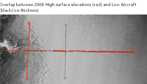
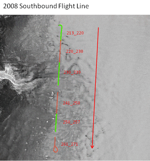
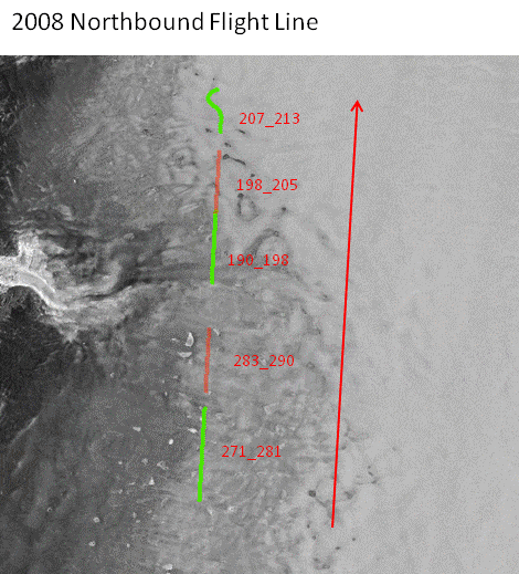
Thick red line = high elevation, Thin black dotted line = low aircraft elevation
Products
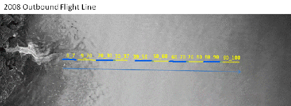
products for segment 0_7 | 0_7.thickness.tiff
products for segment 9_20 | 9_20.thickness.tiff
products for segment 20_30 note: 20_30 data segment corrupt. Intenstity graphic and ASCII file only
products for segment 30_37 | 30_37.thickness.tiff
products for segment 39_50 | 39_50.thickness.tiff
products for segment 50_60 | 50_60.thickness.tiff
products for segment 60_70 | 60_70.thickness.tiff
products for segment 70_80 | 70_80.thickness.tiff
products for segment 80_90 | 80_90.thickness.tiff
products for segment 90_100 | 90_100.thickness.tiff
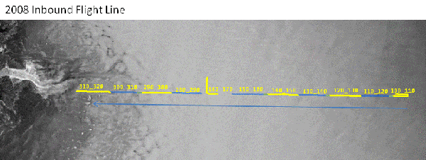
products for segment 100_110 | 100_110.thickness.tiff
products for segment 110_120 | 110_120.thickness.tiff
products for segment 120_130 | 120_130.thickness.tiff
products for segment 130_140 | 130_140.thickness.tiff
products for segment 140_150 | 140_150.thickness.tiff
products for segment 150_160 | 150_160.thickness.tiff
products for segment 162_170 | 162_170.thickness.tiff
products for segment 280_290 | 280_290.thickness.tiff
products for segment 290_300 | 290_300.thickness.tiff
products for segment 300_310 | 300_310.thickness.tiff
products for segment 310_320 | 310_320.thickness.tiff
products for segment 190_200 | 190_200.thickness.tiff
products for segment 200_210 | 200_210.thickness.tiff
products for segment 210_220 | 210_220.thickness.tiff
products for segment 220_230 | 220_230.thickness.tiff
products for segment 230_240 | 230_240.thickness.tiff
products for segment 240_250 | 240_250.thickness.tiff
products for segment 250_260 | 250_260.thickness.tiff
products for segment 260_270 | 260_270.thickness.tiff
products for segment 270_280 | 270_280.thickness.tiff
products for segment 162_170 | 162_170.thickness.tiff
products for segment 170_180 | 170_180.thickness.tiff
products for segment 180_190 | 180_190.thickness.tiff
2008 High Aircraft Elevation Data Products
Each flight line was segmented into approximately 25km long sections with 20% overlap on each end. Each segment contains the following data in a zip file:
1. Elevation data 32 bit float binary, 20m pixel resolution ‘seg#_elevation’
2. Elevation data GEOtiff, 20m, ‘seg#_elevation_geo.tif’
3. Elevation data graphic ‘seg#.elevation.tiff’
4. Image data 32 bit float binary, 20m pixel resolution ‘seg#_image’
5. Image data GEOtiff, 20m, ‘seg#_image_geo.tif’
6. Header file with columns, rows, projection information, and corner map coordinates ‘seg#.hdr’
7. Base Intensity data 32 bit float binary, 5X25m (pixel x line) resolution which include both the surface and base part. This slant range image can be used to get the nadir elevation information and as a reference to the elevation maps. ‘seg#_base_inten’
8. Azimuth compressed header file with column, row, resolution, wavelength, and # looks ‘seg#_0_0.azcom.par’
9. Azimuth compressed nadir file with latitude, longitude of first pixel of each azimuth line in the slant range image and roll angle in degrees (last column) ‘seg#_0_0.azcom.nadir’
10. Surface/Base profile gives an estimate (may not be exact in some areas) of the surface and the base profile. ‘seg#_surface_base.profile’ *note: not all segments have this file*
Ice_thickness = (base_pixel – surface_pixel)*5.0/1.8(m)
‘seg#’ refers to the segment number ie: 0_3, 3_7, 7_11, 100_110 etc.
Low aircraft elevation data and high elevation data overlap.

thick red line = high elevation
thin black dotted line = low aircraft elevation
Products

products for segment 20_30 | 20_30.elevation.tiff
no surface_base.profile file
products for segment 32_40 | 32_40.elevation.tiff
products for segment 40_45 | 40_45.elevation.tiff
products for segment 47_53 | 47_53.elevation.tiff
products for segment 55_60 | 55_60.elevation.tiff
no surface_base.profile file
products for segment 60_69 | 60_69.elevation.tiff
products for segment 71_80 | 71_80.elevation.tiff
products for segment 80_90 | 80_90.elevation.tiff

products for segment 90_100 | 90_100.elevation.tiff
products for segment 100_108 | 100_108.elevation.tiff
products for segment 108_113 | 108_113.elevation.tiff
products for segment 115_120 | 115_120.elevation.tiff
products for segment 130_139 | 130_139.elevation.tiff
products for segment 141_145 | 141_145.elevation.tiff
no surface_base.profile file
products for segment 147_155 | 147_155.elevation.tiff
products for segment 155_162 | 155_162.elevation.tiff
no surface_base.profile file
products for segment 166_173 | 166_173.elevation.tiff
products for segment 173_180 | 173_180.elevation.tiff
products for segment 180_190 | 180_190.elevation.tiff

products for segment 213_220 | 213_220.elevation.tiff
no surface_base.profile file
products for segment 220_230 | 220_230.elevation.tiff
products for segment 230_239 | 230_239.elevation.tiff
products for segment 241_250 | 241_250.elevation.tiff
products for segment 250_257 | 250_257.elevation.tiff
products for segment 261_271 | 261_271.elevation.tiff

products for segment 190_198 | 190_198.elevation.tiff
products for segment 198_205 | 198_205.elevation.tiff
products for segment 207_213 | 207_213.elevation.tiff
products for segment 271_281 | 271_281.elevation.tiff
products for segment 283_290 | 283_290.elevation.tiff
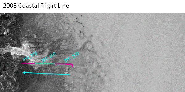
products for segment 290_300 | 290_300.elevation.tiff
products for segment 300_310 | 300_310.elevation.tiff
no surface_base.profile file
products for segment 310_316 | 310_316.elevation.tiff
no surface_base.profile file
Publications and Conference Presentations
| Venue | Year | Format | Link |
|---|---|---|---|
| AGU | 2005 | Abstract | AGU Abstract |
| WAIS | 2005 | Poster | WAIS Poster |
| Journal of Geophysical Research: Planets | 2006 | Journal article | JGR Article |
| EUSAR | 2006 | Conference paper | EUSAR Paper |
| AGU | 2006 | Abstract | AGU Abstract |
| EUSAR | 2008 | Conference paper | EUSAR Paper |
| EUSAR | 2010 | Conference paper | EUSAR Paper |
| TGARSS | 2010 | Conference paper | TGARSS Paper |